Table of Contents
Advertisement
Quick Links
Advertisement
Table of Contents

Related Manuals for Amb-OS Media AMR-100-I


Summary of Contents for Amb-OS Media AMR-100-I
- Page 1 Amb-OS Media, LLC AMR-100-I Operations Manual Firmware 2.03 Version 1 01/12/12...
- Page 2 Rev. 1 – Firmware version 2.03 © 2012...
-
Page 3: Table Of Contents
TABLE OF CONTENTS CONTENTS OF PACKAGE ......................5 INTRODUCTION ........................... 5 General Information ........................5 Help ............................5 Overview of Connections and controls ..................6 Getting Started ........................6 Audio ..........................7 Power ..........................7 Boot Process ........................7 Ethernet Connection ......................9 Error Conditions ........................ - Page 4 Digital ..........................35 Streaming ........................... 35 Playback after a power loss ......................36 HTML INTERFACE ........................37 Access to the AMR-100-I Web page ..................37 General diagnostics ........................38 System Statistics ........................ 38 General Statistics: ......................38 Data Statistics ........................39 Stream Statistics .......................
-
Page 5: Contents Of Package
CONTENTS OF PACKAGE 1 – AMR-100-I AMB-OS Receiver 1 – AC power cable 1 – Quick Installation Guide INTRODUCTION General Information Help If you experience a problem with your installation or just need technical help, call: 1-877-AMBOS2U 1-877-262-6728 or visit: www.amb-os.com... -
Page 6: Overview Of Connections And Controls
Section. To have programs permissioned for your receiver, send an email to programs@amb-os.com with the list of the programs you want to receive. The Ethernet cable should not be plugged into the AMR-100-I until after the first boot so you can configure the IP Address... -
Page 7: Audio
NOTE There is no power switch, the front panel light is only an indicator of power. Boot Process After the AMR-100-I receives power, it begins its startup process. 1. Reset the drive 2. Initialize the drive Rev. 1 – Firmware version 2.03 ©... - Page 8 4. All of the “I/O” boxes on the top line should be clear (no alarms). WARNING To preserve the AMR-100-I status logs, always use the reset switch to reset the receiver. Never unplug the receiver to reboot it. Rev. 1 – Firmware version 2.03 ©...
-
Page 9: Ethernet Connection
Ethernet section. The Ethernet connection allows The AMR-100-I to receive programs from the uplink servers and also allows copying files from the AMR-100-I to another computer. It is possible to use only the Ethernet connection for file copying and never play programs out the audio ports. -
Page 10: General Description
GENERAL DESCRIPTION File Reception The AMR-100-I receives programs as audio files via the Internet and stored on an internal hard drive. The audio files must either be scheduled to played out the audio ports or copied to your automation system. Please see the Amb-OS User Interface to schedule and copy programs. -
Page 11: Target Maps
All targets need to use the audio ports as the primary target. If you want to stream a program on your internal network on target T224.0.0.1:5004, the program also will have to use an audio port. The AMB-OS transfer program will require you to enter which audio port you want to use. -
Page 12: Digital Ports
Grace to You summed to mono. Playlist The AMR-100-I has a playlist that controls when files are played and what can trigger a file playback. It also works with live feeds to insert spots and produce relay closures. The playlist is managed by the AMB-OS User Interface (UI) that transfers programs. -
Page 13: Triggers
Triggers Triggers initiate an action on the AMR-100-I receiver. An input closure can be used to start a file playing and another input closure can cause the file to stop playing. Wiring a switch to a start button on the board can be wired to input closure #1. A trigger can be set up to play a file whenever that button is pressed. -
Page 14: Fault Indications By Relay #6
Time Sync by Relay #5 To keep clocks synchronized at your station, a time pulse can be used from the AMR-100-I. Every hour, relay #5 can close for one second as a time sync pulse. This can be at any minute and second of the hour. -
Page 15: Closure Map Definitions
would trigger or it would set your time. You must go back to the Relay Map area and change that function from relay #5 to another available relay. Closure Map definitions The following table describes the default mapped relays. Relay names and Default assignments: Descriptions Name Relay # State –... -
Page 16: Resetting The Receiver's Display To Its Default Setting
Because the clock is accurate, a relay, typically relay #5 can be used to keep your local clocks in sync. The time sync (see Clock Interval section) can be set for any minute and second. Resetting the receiver's display to its default setting At times it may be necessary to reset your receiver to the factory settings. -
Page 17: Detailed Description And Operations
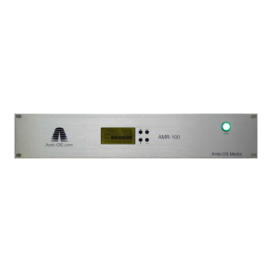
DETAILED DESCRIPTION AND OPERATIONS Front Panel Description The front panel display gives the status of the receiver. The main screen shows relays, audio output, and the status of the RF and Ethernet (see Front Panel section). Front Panel Buttons To the right of the display are four buttons: [UP] arrow [BACK] [DOWN] arrow... -
Page 18: Rear Panel Description
Rear Panel Description Connections The AMB-OS AMR-100-I Receiver has several connections to facilitate program playback and transfers. The connectors are: 10 11 1. Power – A standard computer type power cable is used 2. RF – F-type Connector: Not used in the AMR-100-I 3. -
Page 19: Installation
INSTALLATION Audio Analog The analog audio connectors are standard XLR connectors. Remember, there are two stereo ports or targets on the receiver. The output of these will be discussed in detail later, but each of the two ports can be played in stereo (2 stereo ports), all mono (4 mono ports) or mixed (1 port stereo and the other 2 mono channels). -
Page 20: Ip Address Change
one or two digit subnet addresses should have leading 0’s. For Example: 192.168.1.20 should be entered as: 192.168.001.020. WARNING If you put in an IP address manually, you must also put in the subnet mask and the default gateway. If not, you cannot exit the IP Address menu. IP Address Change Date Setup... -
Page 21: Relay Specifications
Relay Specifications One side of each of the utilized input closures needs to be shorted to ground, pin 7, to create a closure circuit. A rail voltage, pin 13, is supplied to pull up the other side of the input. The shield is also a ground connection. - Page 22 The following diagram shows the use of a +5V external pull-up source. Rev. 1 – Firmware version 2.03 © 2012...
-
Page 23: Operations
Emergency Message Enabled: This indicates whether the AMR-100-I will receive a broadcast on TMAP7. This enables the AMR-100-I to receive a special broadcast or if there is an emergency broadcast for the entire network. To receive these broadcasts, TMAP7 must have an assigned audio port and the “*”... -
Page 24: Deauthorized Message
Deauthorized Message: The Amb-OS system administrators can disable a receiver. If that happens, the following message appears on the screen with only the message line below it: Deauthorized In the event your receiver becomes “Deauthorized,” you need to call AMB-OS to have it restored to normal operation. -
Page 25: Front Panel Menu Options
Front Panel Menu Options The following chart is a tree of all the options in the front panel setup. Settings Firmware Serial IP_Addr Alarm DHCP IP Addr Gateway Netmask Servers 1-8 Ports 1-8 Cmd Addr Cmd Port Web Port Clock Interval Closure Map Minutes P1LS... - Page 26 The SETTINGS display shows the following options and the “*” indicates setting has optional parameters, but the “*” is not on the screen. Firmware: 2.03 (or current version) Serial No: 2001000 (your serial number) Addr: 192.168.1.100 (an example of an internal IP address only) *Clock Interval *Closure Map *Target Map...
-
Page 27: Settings Menu
Settings Menu IP Address Submenu MAC XXXXXXXXXXXX (unique to each receiver and cannot be changed) IP Addr *Alarm: ON (default – assigned to Relay #6) The alarm closes on the following conditions: Alarm 1. Loss of Ethernet connectivity to the network DHCP 2. - Page 28 Never change the IP addresses of the servers or the ports unless you are instructed to do so by Amb-OS support personnel. Changing the ports can cause the AMR-100-I to miss programs. The default IP addresses for each server is: RpSrvr 1: 72.159.94.35...
- Page 29 *CmdAddr: 239.239.239.128 (This should never be changed unless instructed to do so by Amb-OS support personnel. It is the port used to send commands to the AMR-100-I receiver. Remember 1 and 2 digit subnet addresses have leading 0’s (.002. for .2. and .
- Page 30 *Alarm: ON (default) Relay #6 closes on any of the following conditions: 1. Loss of a local area network connection 2. Loss of Internet connection to the uplink server To turn the alarm off, use the following procedure. 1. Press [ENTER] to access the menu. 2.
-
Page 31: Resetting To Default Closures
General instructions: 1. [ENTER] moves between fields and accepts changes 2. [BACK] goes to a previous field and saves the setting only when you are on the name of the relay (P1LS, P1LE, etc.) 3. [UP] and [DOWN] change values Changing settings: 1. - Page 32 If you adjust the display to an unreadable condition, you can restore the display by using a “Cold Boot.” This is done by unplugging the AMR-100-I receiver and press and hold the [ENTER] button as you plug in the AMR-100- I.
-
Page 33: Date Menu
Date Time: The receiver wakes up based on the time setting it had during testing at the factory. You may change this only before the AMR-100-I syncs its time. Time Zone: Zone: Eastern (default) The zone can be set to any time zone. - Page 34 In addition to the GMT hour settings, it is possible to change the GMT by minutes using the Zmins (Zone Minutes) setting. If your time zone does not fall on the exact hour, you can change the minutes of your time zone by using the up and down arrows.
-
Page 35: Audio Playback Description
4 mono programs: 2 on each port – 1 on Port 1-L, 1 on Port 1-R, 1 on Port 2-L and 1 on Port 2-R The AMR-100-I will mix a stereo program to mono when you send it out a mono port. A stereo program sent out Port 1-L will have the left and right mixed to mono on that port. -
Page 36: Playback After A Power Loss
2. At 9:09:45 power was lost to the receiver and audio terminated 3. Power was restored at 9:11:20 4. The AMR-100-I, after rebooting, will resume audio at approximately 9:11:50 5. The audio will play what was supposed to be playing at 9:11:50 had the power not... -
Page 37: Html Interface
Your IP Address was set at the beginning of the installation. However, if you do not remember what that was, go to the AMR-100-I and press the [DOWN] arrow and it will be next to the IP Addr: line. -
Page 38: General Diagnostics
Ethernet Addr is MAC address of the AMR-100-I *DHCP describes is the IP address is selected automatically *IP Address is the internal network address of the AMR-100-I *Netmask is the network mask *Gateway is the address of the Internet gateway of your internal network... -
Page 39: Audio Statistics
TMAP7 Armed: Target Maps (TMAP) allow the AMR-100-I to use a different physical output for the same name. Live streams can send a program to a TMAP number and the station can have the program come out their port or target. TMAP7 is reserved for emergency or ad hoc broadcasts. -
Page 40: Drive Statistics
Space Left: 74078Mb Open Files reports the number of files open for playback on the AMR-100-I. If you had four mono files playing, that number would be 4. Space Used reports the amount of drive space with data (used space). -
Page 41: Scheduled Event List
The column labeled Action has the following entries: OPEN/SEEK is when the AMR-100-I “cues” the file. It does that one second before it plays. PLAY shows that it will play at 01:30:00. STOP shows when the file will end at 01:52:00. - Page 42 The Time column shows when each event will happen. The Source column shows the exact name of the file that will play. Target shows the port that will be used to play the file. Level shows the starting, playing and ending volume (-inf = off, 0dB = full volume).
-
Page 43: Trigger Event Lists
Trigger Event Lists This link takes you to a page listing events that happen on an input closure or on a command sent by satellite or serial port. The system calls these trigger events. If an event happens on a closure sent by a program producer, then it will have a serial string that causes a program or spot to air. -
Page 44: Command Interface
Command Interface This page allows you to send commands to the receiver. The image below has the list of commands and a brief description of those commands. The window is where the command is typed then you press Execute. For example to close Relay #1, you type “relay 1 on” and then press Execute. -
Page 45: General Commands
General Commands REBOOT This causes the system to be rebooted. Audio playing from a timed event (see Schedules) will restart at the point it would have been had the system not been rebooted. WARNING Rebooting will cause the receiver to quit playing audio! Syntax: REBOOT RELAY # ON/OFF This will close the relay specified in the command. -
Page 46: Set Dst
DHCP Router. That is usually in a router or high-speed (DSL or cable) modem. Syntax: DHCP ON or DHCP OFF NEWIP #.#.#.# This allows you to set the IP address of the AMR-100-I receiver. Your network administrator must provide this address if DHCP is set to OFF. Syntax: NEWIP 192.168.1.145 NEWNETMASK #.#.#.# The Netmask is a filter that rejects or accepts communications from other computers on the network. -
Page 47: Webport
WEBPORT # Sets the Web or HTTP port number. This is normally set to 80, but at times an installation will have more than web interface device and another port may be needed. The other typical number is 8080. Syntax: WEBPORT 8080 Rev. -
Page 48: Audio Control Commands
Audio Control Commands AUDPLAY Plays a specified file on a target on the receiver. This function needs the exact file name to play correctly. It will not mix two programs together, but it will sum a program to a mono source. -
Page 49: Tstop
A section under the system statistics shows the current mapping on the AMR-100-I receiver. The target can be any one of seven targets: T1 = Port 1 stereo T1L = Port 1 mono – left side only T1R = Port 1 mono – right side only T2 = Port 2 stereo T2L = Port 2 mono –... -
Page 50: Troubleshooting Chart
TROUBLESHOOTING CHART The following chart shows basic problems and solutions. For troubleshooting trees go to the following web site. www.amb-os.com/trouble.html Symptom Cause Solution No power No power applied to the unit 1. Verify the AC cable is properly inserted indicator light 2. - Page 51 correctly 3. Verify the proper audio port or target is being Playlist is incorrect used 4. Verify the proper audio channel is being monitored on the board 5. Verify the proper audio target is selected in the playlist (see the Amb-OS User Interface Manual or the Playlist Manual available on www.amb- os.com/support.html)
-
Page 52: Definitions
DEFINITIONS Daylight Saving Time – The practice of changing the time during the summer by one hour to have more daylight during waking hours. www.nist.gov/physlab/div847/localtime.cfm DHCP or Dynamic Host Configuration Protocol – A system of assigning IP addresses to computers on a network to avoid conflicts of having more than one computer having the same IP address.
Need help?
Do you have a question about the AMR-100-I and is the answer not in the manual?
Questions and answers