Table of Contents
Advertisement
Quick Links
Advertisement
Table of Contents

Related Manuals for General CMR35 Series


Summary of Contents for General CMR35 Series
- Page 1 CMR35 Manual FINAL4_020911:awb 2/9/11 11:54 AM Page 1 WIRELESS MULTI-NODE DATA LOGGING TRUE RMS CLAMP MULTIMETER SYSTEM USER’S MANUAL Receiver Transmitter CMR35 SERIES CMR35–910MHz CMR35A–912.4MHz Please read this manual carefully and thoroughly before using this product.
-
Page 2: Table Of Contents
CMR35 Manual FINAL4_020911:awb 2/9/11 11:54 AM Page 2 TABLE OF CONTENTS Introduction ............3 Safety Precautions . -
Page 3: Introduction
CMR35 Manual FINAL4_020911:awb 2/9/11 11:54 AM Page 3 INTRODUCTION Thank you for purchasing General Tools & Instruments’ CMR35 Series Wireless Data Logging Clamp Multimeter System. Please read this user’s manual carefully and thoroughly before using the instrument. There are two CMR35 systems: The CMR35 system operates at 910MHz and the CMR35A system operates at 912.4MHz. -
Page 4: Key Features
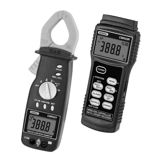
• Stores and recalls minimum and maximum readings WHAT’S IN THE CASE The two main components of the CMR35 Series system—the clamp meter/transmitter (CMR35T transmitter) and the data logging receiver (CMR35R receiver)—come in a protective hard carrying case along with a pair of probes, four “AA” batteries (two each for the transmitter and receiver), a USB cable, an installation CD containing Excel-compatible data logging software and a USB driver, and this user’s manual. -
Page 5: Product Overview
CMR35 Manual FINAL4_020911:awb 2/9/11 11:54 AM Page 5 PRODUCT OVERVIEW Before using the transmitter and receiver together, learn how to make some basic measurements using the transmitter unit alone. To begin, familiarize yourself with Figures 1 and 2. Fig. 1 shows the transmitter unit’s controls, indicators and jacks. Fig. 2 shows the symbols used by the transmitter’s liquid-crystal display, as well as their positions. - Page 6 CMR35 Manual FINAL4_020911:awb 2/9/11 11:54 AM Page 6 Symbol Description Transmission ID code (Channel) setting Antenna blinking while in the process of transmitting Transmission span selection; options are 2, 10, 30, 60, and 120 seconds Lit in DC voltage measurement mode Lit in AC voltage measurement mode Lit when measuring negative polarity Autoranging on indicator...
-
Page 7: Operating Instructions
To measure the current drawn by an appliance with a fixed power cord, General recommends using an industry-standard AC line splitter, as shown in the following figure. To purchase an AC line splitter from General, see p. -
Page 8: Measuring Voltage
CMR35 Manual FINAL4_020911:awb 2/9/11 11:54 AM Page 8 In DC current measurement mode, the CMR35T selects a 0 to 400A measurement range unless the input is greater than 400A. In this case, the unit automatically switches to a full-scale range of 0 to 600A. Read the value after it stabilizes. -
Page 9: Measuring Resistance
CMR35 Manual FINAL4_020911:awb 2/9/11 11:54 AM Page 9 • WARNING • To avoid exposing yourself to a harmful or a fatal voltage and damaging the transmitter, make sure that the potential you are attempting to measure is less than 600VAC. As in current measurement mode, the CMR35T automatically chooses the narrowest measurement range that includes the tested value. -
Page 10: Measuring Frequency
CMR35 Manual FINAL4_020911:awb 2/9/11 11:54 AM Page 10 RED PROBE BLACK PROBE A “good” silicon diode should produce a reading of 0.5 to 0.7V. A “good” GE diode should produce a reading of 0.2 to 0.3V. If the reading is close to “0”, the diode is short- circuited. -
Page 11: Making Relative Measurements
CMR35 Manual FINAL4_020911:awb 2/9/11 11:54 AM Page 11 • WARNING • To avoid exposing yourself to a harmful or a fatal voltage and damaging the transmitter, make sure that the AC voltage or current whose frequency you are measuring has an amplitude of less than 600V. As in current measurement mode, the CMR35T automatically chooses the narrowest measurement range that includes the tested value. -
Page 12: Using The Receiver With The Transmitter
CMR35 Manual FINAL4_020911:awb 2/9/11 11:54 AM Page 12 USING THE RECEIVER WITH THE TRANSMITTER Three buttons on the front panel of the transmitter must be pressed to prepare it to wirelessly send readings to the receiver. One is the TX ON button (callout 9 of Fig. 1). Pressing this button activates transmission mode and causes the symbol to appear at the upper left of the display, as shown in the figure below. - Page 13 CMR35 Manual FINAL4_020911:awb 2/9/11 11:54 AM Page 13 Transmission span setting ID code (Channel) setting Before moving on to operating the receiver, familiarize yourself with Figures 3 and 4. Fig. 3 shows the controls, indicators and jacks of the receiver. Fig. 4 shows the symbols used by the receiver’s liquid-crystal display and their positions.
- Page 14 CMR35 Manual FINAL4_020911:awb 2/9/11 11:54 AM Page 14 RIGHT SIDE Fig. 3. The receiver’s controls, indicators and jacks Nameplate Liquid-crystal display POWER button READ button. Main use is for recalling stored maximum and minimum measurements. Secondary function (indicated by ▲ stencil at right of button) is for adjusting settings of clock and alarm HOLD MAX-H button.
- Page 15 CMR35 Manual FINAL4_020911:awb 2/9/11 11:54 AM Page 15 Symbol Description Transmission ID code (Channel) setting (1 to 6) When blinking, indicates signal being received from transmitter Indicates displayed value is memorized maximum or minimum measurement Indicates displayed value is recalled maximum or minimum measurement Lit in alarm mode when measured value is higher or lower than alarm setpoint Lit in 24-hour clock mode Lit in DC voltage measurement mode...
-
Page 16: Operating The Receiver
CMR35 Manual FINAL4_020911:awb 2/9/11 11:54 AM Page 16 OPERATING THE RECEIVER To power on, press the button. To power off, press the button and hold it for at least three seconds. READING, HOLDING, STORING AND RECALLING DATA To use the button to recall stored maximum or minimum values, follow the instructions embedded in the next two figures. - Page 17 CMR35 Manual FINAL4_020911:awb 2/9/11 11:54 AM Page 17 To use the button to hold the current reading: To enter MAX-HOLD mode and recall MAX measurements: To use the button to store maximum and minimum values, follow the instructions embedded in the next figure.
-
Page 18: Setting Alarms And Setpoints
CMR35 Manual FINAL4_020911:awb 2/9/11 11:54 AM Page 18 To use the secondary function of the button to move the position of the blinking digit when setting the clock and alarm, refer to the figure below. When the digit is blinking, press the key to move to the next digit. - Page 19 CMR35 Manual FINAL4_020911:awb 2/9/11 11:54 AM Page 19 To set an alarm setpoint Press ALARM button to enter alarm function mode Press SEARCH button Enter setpoint setting mode. Receiver will return to measuring mode if ► or ▲ button is not pressed when disappears Press ►...
-
Page 20: Setting The Clock
CMR35 Manual FINAL4_020911:awb 2/9/11 11:54 AM Page 20 SETTING THE CLOCK button to enter clock setting mode. You must then press the ▲ or ► Press the button within two seconds or the first screen below will disappear. To set the clock button, and then press ▲... - Page 21 CMR35 Manual FINAL4_020911:awb 2/9/11 11:54 AM Page 21 ID code (Channel) setting Press SEARCH button and hold for two seconds to enter ID code selection mode Press CLOCK SET button to switch selected ID Code (Channel) on or off Press CHANNEL button to switch to different ID code ID code (Channel) (Channel)
-
Page 22: Data Logging With A Computer
2. After the CD loads, an AutoPlay screen for the CMR35_V1.0.20 software will appear. Left-click “Run autorun.exe”. 3. The next screen to appear is an Adobe Flash Player 9 screen with the General logo at upper left and “CMR35” at upper right. Left-click the “Software Installation”... -
Page 23: Verifying The Installation
CMR35 Manual FINAL4_020911:awb 2/9/11 11:54 AM Page 23 10. The CMR35 Flash Player 9 screen will reappear on your desktop. Left-click the “USB Installation” button. 11. The next screen will be a File Download-Security Warning. Respond to the question “Do you want to run or save this file?” (the 20.0KB InstallUSB.exe file) by clicking Run. -
Page 24: Using The Software
CMR35 Manual FINAL4_020911:awb 2/9/11 11:54 AM Page 24 USING THE SOFTWARE To use the software, refer to the callouts accompanying the following partial screen shots. Each screen shot and set of callouts detail the functions available from one of the pull-down buttons on the software’s main menu bar. - Page 25 CMR35 Manual FINAL4_020911:awb 2/9/11 11:54 AM Page 25 The Edit menu The View menu The four options above also are available from the toolbar below the main menu, as shown below The Table window...
- Page 26 CMR35 Manual FINAL4_020911:awb 2/9/11 11:54 AM Page 26 The Monitor window The Graph window The Electric Power Cost Monitor window Display of this window can be enabled using the View menu or the toolbar below the main menu. However, the Electric Power Cost Monitor window will display only if the three parameters in the bottom row—V, P.F.
- Page 27 CMR35 Manual FINAL4_020911:awb 2/9/11 11:54 AM Page 27 If you know the line voltage of your system, enter it in the “V” window at left (110V is shown). If you are not sure of the line voltage, measure it by inserting the transmitter’s black and red probes in a power outlet.
- Page 28 CMR35 Manual FINAL4_020911:awb 2/9/11 11:54 AM Page 28 The Option menu Table tab Select table background color and type of grid line (flat, inset or raised)
- Page 29 CMR35 Manual FINAL4_020911:awb 2/9/11 11:54 AM Page 29 The Window menu Returns Monitor, Table, Graph and Electric Power Cost Monitor windows to default positions The Help menu Open Wireless Clamp Meter User’s Manual. Windows, Windows 7, Windows Vista and Windows XP are registered trademarks of Microsoft Corporation.
-
Page 30: Specifications
CMR35 Manual FINAL4_020911:awb 2/9/11 11:54 AM Page 30 SPECIFICATIONS ELECTRICAL SPECIFICATIONS AC Current Measurement Maximum Range Resolution Accuracy input current 400A 0.1A ±(1.8% of reading + 10 digits) 600A 600A 600A ±(1% of reading + 5 digits) DC Current Measurement Maximum Range Resolution... - Page 31 CMR35 Manual FINAL4_020911:awb 2/9/11 11:54 AM Page 31 Resistance Measurement Maximum Range Resolution Accuracy Remarks input voltage 400Ω 0.1Ω 4kΩ 0.001kΩ ±(1% of reading --Open circuit + 5 digits) 40kΩ 0.01kΩ voltage is ~0.4V --Measuring current 400kΩ 0.1kΩ 600V varies with 4MΩ...
- Page 32 CMR35 Manual FINAL4_020911:awb 2/9/11 11:54 AM Page 32 GENERAL SPECIFICATIONS Distance between 333 ft. (100m) maximum; less with obstacles in path and transmitter and receiver when either unit is inside metallic structure Transmission frequency 910MHz (CMR35) or 912.4MHz (CMR35A) Sampling rate Three times/second with no transmission;...
-
Page 33: Fcc Radio Frequency Interference Compliance Disclosure
CMR35 Manual FINAL4_020911:awb 2/9/11 11:54 AM Page 33 FCC RADIO FREQUENCY INTERFERENCE COMPLIANCE DISCLOSURE This device complies with Part 15 of U.S. Federal Communications Commission (FCC) rules governing radio frequency devices. Operation is subject to the following two conditions: (1) this device may not cause harmful interference, and (2) this device must accept any interference received, including interference that may cause undesired operation. -
Page 34: Operation And Maintenance Tips
Acceptance of the exclusive repair and replacement remedies described herein is a condition of the contract for purchase of this product. In no event shall General be liable for any incidental, special, consequential or punitive damages, or for any cost, attorneys’ fees, expenses, or losses alleged to be a consequence of any damage due to failure of, or defect in any product including, but not limited to, any claims for loss of profits. -
Page 35: Return For Repair Policy
Customer Service to obtain an RGA (Return Goods Authorization) number before forwarding the unit via prepaid freight to the atten- tion of our Service Center at this address: General Tools & Instruments 80 White Street New York, NY 10013... - Page 36 New York, NY 10013-3567 PHONE (212) 431-6100 FAX (212) 431-6499 TOLL FREE (800) 697-8665 e-mail: sales@generaltools.com www.generaltools.com CMR35 Series User’s Manual Specifications subject to change without notice ©2011 GENERAL TOOLS & INSTRUMENTS NOTICE - WE ARE NOT RESPONSIBLE FOR TYPOGRAPHICAL ERRORS. MAN#CMR35 2/9/11...
Need help?
Do you have a question about the CMR35 Series and is the answer not in the manual?
Questions and answers