
Subscribe to Our Youtube Channel
Related Manuals for General DMM550


Summary of Contents for General DMM550
- Page 1 RUGGED TRUE RMS MULTIMETER WITH NCV DETECTION USER’S MANUAL DMM550 Please read this manual carefully and thoroughly before using this product.
-
Page 2: Table Of Contents
Operating Instructions....9 – 19 General Instructions ....9 – 12 Ranging Options . -
Page 3: Introduction
(General’s) DMM550 Rugged True RMS Multimeter with NCV Detection. Please read this user’s manual carefully and thoroughly before using the instrument. The DMM550 is designed for use in an industrial setting by HVAC/R contractors, building maintenance technicians, MRO (maintenance, repair and operations) personnel at process and power plants, electricians and electrical/electronic technicians. -
Page 4: What's In The Box
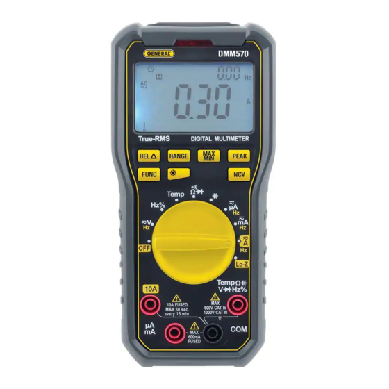
PRODUCT OVERVIEW Fig. 1 shows the labels and positions of the controls, indicators and physical structures of the DMM550. Fig. 2 shows all possible indications on the LCD. Familiarize yourself with the functions and meanings of these controls, indicators and connectors before moving on to the Setup Instructions and Operating Instructions. - Page 5 • RANGE: Switches between Auto ranging and Manual ranging modes (see p. 9) • MAX/MIN: Enters Max/Min mode (see p. 10), in which the secondary display shows the largest and smallest values of any parameter since switching to measure it. •...
-
Page 6: Safety Instructions
SAFETY INSTRUCTIONS •• •• Warning To avoid possible electric shock or personal injury, and to avoid damaging the meter or the equipment under test: • Do not use the meter in any way not detailed in this manual or the meter's safety features may be compromised. - Page 7 • •WARNING Do not operate the meter around explosive gas, vapor, or dust. • •WARNING When using the probes, keep your fingers behind the finger guards. Do not touch the metal probes of the test leads when making a measurement. •...
- Page 8 Electrical Symbols Used On the Meter and In This Manual Symbol Description Symbol Description AC (Alternating Fuse Current) Double (Direct Current) Insulated Caution, risk of Risk of danger. electric shock. Important Hazardous information. voltage. Refer to the manual. Battery (Low battery) Earth ground when shown on display...
-
Page 9: Setup Instructions
SETUP INSTRUCTIONS INSTALL BATTERY The battery compartment of the DMM550 is located at the back of the meter. To open the compartment, use a small Phillips-head screwdriver to remove the single screw securing the battery compartment cover/flip-up stand. Be careful not to lose the small screw. -
Page 10: Holding Readings
operating in the 0 to 400 F full-scale manual range reduces the full-scale range to 0 to 40 F (and improves measurement resolution). The next press of the button reduces the range to 0 to 4 F. When the smallest full- scale range has been reached, the next press of the RANGE button switches the meter back to the largest full- scale manual range for the parameter being measured. -
Page 11: Disabling Auto Power Off (Apo)
(upper) readout. The term REL will appear at the upper left of the LCD to indicate operation in this special mode. In REL mode, the primary (lower) readout shows the difference between ongoing measurements and the frozen value. REL mode is useful for tracking changes in dynamic processes or deviations from baseline readings. -
Page 12: Turning On The Backlight
Turning On the Backlight Pressing the button turns on the LCD’s bright white backlight, making measurements much easier to read in dark spaces. To prevent the backlight from draining the meter’s battery, the backlight automatically extinguishes in 60 seconds. MEASURING AC OR DC CURRENT ••... -
Page 13: Measuring Ac Or Dc Voltage
3000A. The accessory uses induction to convert current readings to millivolt values that can be displayed by the DMM550. For more information or to order, visit www.generaltools.com and enter “FX3000” in the SEARCH box. -
Page 14: Using The Non-Contact Voltage Detector
•• •• Warning The NCV detector in the DMM550 is designed to indicate the presence of AC voltage with an amplitude of 110VAC or greater. However, do not assume that the absence of a positive indication means that the circuit under test is de-energized (not “hot”). -
Page 15: Measuring Resistance
To check whether a line, cable or AC outlet is “hot” (energized), touch it with the top of the meter or bring the top within 1/4 inch of it while pressing and holding the front-panel NCV button. If the beeper sounds repeatedly and the red LED flashes rapidly, the line or outlet is energized. -
Page 16: Checking For Continuity
CHECKING FOR CONTINUITY (1) Turn the rotary function switch to the position. Press the FUNC button once to select the continuity check function. Until the test leads are plugged in, the primary readout will show OL., with the icon of a continuity beeper ( ) above it. -
Page 17: Measuring Capacitance
(7) Read the measured capacitance on the display. MEASURING FREQUENCY AND DUTY CYCLE As described earlier, the DMM550 automatically measures the frequency of measured AC currents and voltages and displays them on the secondary readout. However, the range of frequencies that can be measured and displayed in this way is limited to 10Hz to 1kHz. -
Page 18: Measuring Temperature
MEASURING TEMPERATURE To measure the temperature of a solid, liquid or gas: (1) Turn the rotary function switch to the Temp position. The primary readout will show spurious readings until a thermocouple probe is plugged into the meter’s front-panel jacks. (2) Plug the included plug adapter into the red and black jacks at the bottom front of the meter. - Page 19 (3) Plug the included “K” type thermocouple (or a different “K” type thermocouple) into the adapter. Make sure to insert the slightly wider blade of the thermocouple into the – (negative) slot of the adapter. (4) To measure a surface temperature, firmly attach the tip of the thermocouple to the surface.
- Page 20 Parameter or Feature/Function Attribute Frequency (with rotary function switch Measurement ranges position) Measurement accuracy Capacitance Measurement ranges Measurement accuracy Continuity Open circuit voltage Threshold Diode integrity Reverse DC voltage Forward DC current Duty cycle Measurement range Measurement accuracy/ resolution Temperature Measurement range Measurement accuracy (excluding thermocouple)
- Page 21 Specification 10Hz to 40Hz/400Hz/4kHz/10kHz for inputs >0.2VAC ±(1.5% of reading + 5 digits) 0 to 4nF/40nF/400nF/4 F/40 F/400 F/4mF/40mF ±(4% of reading+ 5 digits) in 4nF, 4mF and 40mF ranges; ±(3% of reading+ 3 digits) in other ranges ~1.0V 50Ω ~3.2V ~1mA 1 to 99%...
-
Page 22: Operating & Maintenance Tips
(although measurements will remain valid for several hours after the icon first appears). To replace the battery, follow the instructions on p. 9. Do not operate the DMM550 in the presence of a flammable or explosive gas or near an arc welder or induction heater. -
Page 23: Return For Repair Policy
Acceptance of the exclusive repair and replacement remedies described herein is a condition of the contract for purchase of this product. In no event shall General be liable for any incidental, special, consequential or punitive damages, or for any cost, attorneys’ fees,... - Page 24 FAX (212) 431-6499 TOLL FREE (800) 697-8665 e-mail: sales@generaltools.com www.generaltools.com DMM550 User’s Manual Specifications subject to change without notice ©2014 GENERAL TOOLS & INSTRUMENTS NOTICE - WE ARE NOT RESPONSIBLE FOR TYPOGRAPHICAL ERRORS. MAN# DMM550 7/9/14 General Tools & Instruments GeneralToolsNYC...
Need help?
Do you have a question about the DMM550 and is the answer not in the manual?
Questions and answers