Table of Contents
Advertisement
V A N T A G E C O N T R O L S . C O M
1061 South 800 East • Orem, Utah 84097 • Telephone 801 229 2800 • Fax 801 224 0355
Overview
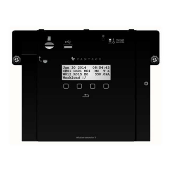
The InFusion™ Controller II is Vantage's
most powerful automation controller to
date, featuring a new, extremely fast
processor
improving
processing
performance.
Systems
using
previous InFusion Controller may be
upgraded by simply plugging in the
new controller,* converting the project
file in Design Center 3.3 or higher and
downloading to the new controller. No changes are needed to the
enclosure or the controller terminal board.
* See Replacing and/or Upgrading InFusion Controllers for
additional information.
Features
•
The InFusion Controller is the main "CPU" of Vantage's
complete systems integration solution
•
Plug and Play design makes it easy to install
•
Automatic crossover support, RJ45 Ethernet connection
•
Secure access – password protected
•
Design Center connection through local network or offsite
Firmware updates, full or minor program changes
o
Auto restore of previous firmware and program
code if update fails.
Diagnostics
o
Read system
o
Project control
o
•
Built-in Ethernet jack
•
Type-A, USB port (future features ready)
The USB port is not used on IC-II controllers to program
o
from Design Center as in previous InFusion controller
models
•
Micro SD card support (included)
•
Automatic System Backups to micro SD card
Manually through front panel – real time
o
Within 24 hours of programming system
o
-then-
Weekly
o
Up to 52 backups total
o
Oldest backup is replaced when 52 limit is reached
o
Backups may be used to program system controllers
o
•
Restore entire system from System Backups
Undo option from last Restore
o
•
Power supply is field serviceable
•
Ram and Flash memory
•
One controller supports up to 120 WireLink™ stations and up to
120 RadioLink™ stations
•
Local LCD interface provides limited control, status and
diagnostics
•
Lithium battery retains time and system status in a power
outage
•
Maintains real and astronomical time clocks
•
Design Center software is used to program the Controller
•
The Controller runs independent of a PC after initial setup and
•
Application code is upgradeable through Design Center
Software
•
InFusion Controllers operate as stand-alone or networked
•
Five Embedded RS-232 Ports
•
Two RS-485 Ports (shared with SE buses 3 and 4; simultaneous
RS-485 and SE bus connections are not possible)
•
Manual Override Switch
•
Reset Switch
•
Built-in Protection, electronic isolation between controllers
•
*The Vantage InFusion Controller Network can have up to
thirty-one Controllers when connected via Ethernet
*15 Controllers maximum on each Controller to Controller
Bus run.
InFusion Controller Specifications
Description
Dimensions HWD
©Vantage, 11/6/2014 / IS-0602-A
the
Specification
6.62" x 7.88" x 3.0"
168mm x 200mm x 76mm
InFusion Controller II — MODEL: IC-36-II & IC-24-II
I N S T A L L A T I O N
InFusion Controller II — MODEL: IC-36-II & IC-24-II
Description
Weight – 24V
Weight – 36V
Voltage
Lightning / Surge
Protection Static Shock IO.
All ports/case
Max. Length of Combined
IC-II to IC-II Bus Network
C2C, IC Network
Station Bus Specification
Each station bus run has a 60W power
Station Bus Power Supply,
supply;
IC-36-II
Station Bus Power Supply,
Shared, 35W max. power supply
IC-24-II
combined to both station bus runs.
609m / 2,000ft of cabling max. on each
Max. Wire Length Station
station bus. No station more than 305m
Bus
Wire Configuration of
Station Bus
Max. # WireLink Stations
Up to 60 Stations each bus or until the
IC-36-II
Max. # WireLink Stations
Up to 50 Stations each bus or until the
IC-24-II
Max. Wire From IC to SE
Maximum Power Draw
IC-36-II
Maximum Power Draw
IC-24-II
Cooling
Lithium Battery Backup
2.5 yrs. un-powered or 20 yrs. powered
(field replaceable – see Caution at end)
Ambient Operating
Temperature
Ambient Operating
Humidity
UL/cUL/CE/FCC
Certified
InFusion Controller II Part Numbers
Part #
IC-24-II
Infusion controller 24V V2
IC-36-II
Infusion controller 36V V2
IC-DIN-II*
Infusion controller - DIN V2
PSU36-DIN
36V, DIN Controller Power Supply
ACPDXXSM2
24V, DIN Controller Power Supply
IC-PWR-36
IC 36 power supply replacement for IC-36-II
IC-PWR-24
IC 24 power supply replacement for IC-24-II
*See, <LINK COMING IC-DIN-II Installation Sheet>
Software/Firmware/Installation Requirements
Design Center Software, version 3.3.X.X or higher must be used to
program controller models with the "-II" at the end of the model
number. Using IC-1 and IC-II controller models on the same system,
is not supported. Installation of Vantage products should be
performed
or
supervised
Disconnect power when plugging in or un-plugging the controller.
The InFusion Controller is plugged into the Main Enclosure
Terminal Board. This board is different for 24V and 36V
controllers. The Main Enclosure Terminal Board is designed to only
accept a Controller that matches the voltage of the Card. Make
sure the IC is firmly seated before tightening locking screws. Please
see Surface Mount Enclosure for wall box and rack mount options.
V A N T A G E I N S T A L L G U I D E S
Specification
3.55 lbs -or- 1.61 kg
4.4 lbs -or- 2 kg
120-240V, 50/60Hz
IEC 61000-4-2
Low Voltage, ITU-T K.20
2000 feet / 609 meters- using
16-18AWG 2-conductor, twisted pair,
non-shielded wire
Ethernet (see Screen 16, p. 4)
2C, 16AWG / 1.31mm2, twisted, non-
shielded, <30pF per foot. Separate a
minimum of 12" / 30.5cm from other
parallel communication and/or high
voltage runs.
•
Station Bus Run 1 = 60W
•
Station Bus Run 2 = 60W
/ 1,000ft from Controller.
Daisy Chain, Branch, Star
(contact support for
Station Bus Best Practices)
60W supply per bus is used
shared 35W supply is used
200 feet / 61 meters
200W
150W
Convection
Disk battery CR2032, 3Volt
0-40°C / 32-104°F
5-95% non-condensing
YES
Description
by
a
Certified
Vantage
Installer.
page 1 of 7
Advertisement
Table of Contents

Subscribe to Our Youtube Channel
Related Manuals for Vantage Hearth InFusion Controller II

Summary of Contents for Vantage Hearth InFusion Controller II
- Page 1 V A N T A G E I N S T A L L G U I D E S InFusion Controller II — MODEL: IC-36-II & IC-24-II 1061 South 800 East • Orem, Utah 84097 • Telephone 801 229 2800 • Fax 801 224 0355...
- Page 2 Main Enclosure Terminal Board – Terminator Switch If one InFusion Controller is used, the Controller Bus Termination switch is always ON. This switch is located on the Main Enclosure ©Vantage, 11/6/2014 / IS-0602-A InFusion Controller II — MODEL: IC-36-II & IC-24-II page 2 of 7...
- Page 3 When a backup has been manually other controllers. executed an Undo option appears in the backup history list. ©Vantage, 11/6/2014 / IS-0602-A InFusion Controller II — MODEL: IC-36-II & IC-24-II page 3 of 7...
- Page 4 I N S T A L L A T I O N ©Vantage, 11/6/2014 / IS-0602-A InFusion Controller II — MODEL: IC-36-II & IC-24-II page 4 of 7...
- Page 5 Design Center with security enabled. b. Users, cannot connect to the controller from Design Center. Users only have Read State and Write State permissions using Host Commands. ©Vantage, 11/6/2014 / IS-0602-A InFusion Controller II — MODEL: IC-36-II & IC-24-II page 5 of 7...
- Page 6 Last Month Email. c. Last Quarter d. User Initiated (only shows when a manual backup operation has been selected) e. Choose Backup by Date ©Vantage, 11/6/2014 / IS-0602-A InFusion Controller II — MODEL: IC-36-II & IC-24-II page 6 of 7...
- Page 7 RS-232/RS-485 Opto (optical) Isolation connection. Opto Isolation provides a communications link and is an important consideration if a system uses different power sources, has noisy signals or must operate at different ground potentials. ©Vantage, 11/6/2014 / IS-0602-A InFusion Controller II — MODEL: IC-36-II & IC-24-II page 7 of 7...
Need help?
Do you have a question about the InFusion Controller II and is the answer not in the manual?
Questions and answers