
Subscribe to Our Youtube Channel
Summary of Contents for Uvar UDI 6Matic 706M002
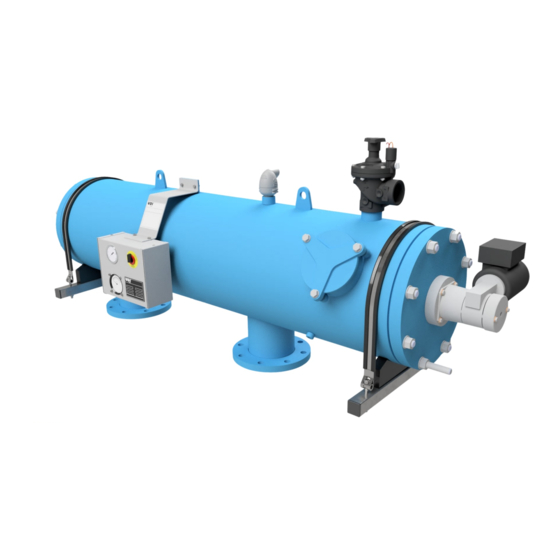
- Page 1 Maintenance Manual - 6Matic. Automatic Screen Filter 6-Matic Installation- Operation- and Maintenance Manual Serial Number UDI 5-3-2020...
- Page 2 Maintenance Manual - 6Matic. UDI 5-3-2020...
-
Page 3: Table Of Contents
Maintenance Manual - 6Matic. INDEX MANUAL 6MATIC 1 - Safety First ....................2 2 - Technical specification.................3 3 - Operating principle................6 4 - Operating modes..................8 5 - Installation procedures.................9 5.1 - Assembly prior to installation.......................9 5.2 - Filter installation...........................9 5.3 - Drain line installation..........................9 5.4 - Electrical installation..........................10 5.5 - Auxiliary filter............................12 6 - First commissioning and routine start-up........13... -
Page 4: Safety First
6Matic. 1 - SAFETY FIRST UVAR believes that the safety of personnel working with and around our equipment is the most important consideration. Please read all safety information below and any other relevant source before attempting to perform any maintenance function. Comply with all approved and established precautions for working with your type of equipment and/or environment. -
Page 5: Technical Specification
Maintenance Manual - 6Matic. 2 - TECHNICAL SPECIFICATION Screen Area & Maximum Flow Rates Model In-/Outlet diameter Max. Flow Rate (*) Flush Flow rate (**) Screen area inch m /h m /h 706M002 2" 2500 706M003 3" 2500 706M034 4" 2500 706M004 4"... - Page 6 Maintenance Manual - 6Matic. Type Connection - B inch 2" 3" 4" 4" 6" 6" 8" 8" 12" Diameter - D inch 12" 12" 12" 12" 12" 16" 16" 16" 16" Flange (ISO 7005 PN10) Pitch Bolt holes mm 4x Ø18 8x Ø18 8x Ø18 8x Ø18 8x Ø22 8x Ø22 8x Ø22 8x Ø22 12x Ø22 Weight Length - L 1480...
- Page 7 Maintenance Manual - 6Matic. Construction The standard housing of the filter is made of carbon steel with a 120 micron protective coating of extra durable polyester, applied electro-statically and oven cured on a zinc-phosphate layer, for maximum anti-corrosion protection both internally and externally. Access to the internal parts of the filter is through the removable bolted cover.
-
Page 8: Operating Principle
Maintenance Manual - 6Matic. 3 - Operating principle A. Filtration mode The raw water enters the filter inlet and passes through the coarse screen (1), the first stage of filtration. This prevents passage of any large particles, which may damage the filter internals. The water then flows through the inside of the filter to the inner side of the fine screen (2). - Page 9 Maintenance Manual - 6Matic. The flushing cycle will be activated on pressure differential, time or manual: 1. When the predetermined differential pressure between inlet and outlet of the filter is reached (as preset on the D.P. Switch, usually 0.5 bar / 0.75 psi). 2.
-
Page 10: Operating Modes
Maintenance Manual - 6Matic. 4 - OPERATING MODES This efficient filter is automatic and easy to operate. When the optional PLC controller is installed the operating modes are as follows: 1. Filtration The normal function of the filter – 2. Automatic Flushing Flushing of the screen through the suction nozzles, activated by time or DP. -
Page 11: Installation Procedures
Maintenance Manual - 6Matic. 5 - Installation procedures 5.1 - Assembly prior to installation The filter is normally supplied fully assembled. Electrical connections will be done by authorized personnel only. The filter may be installed in any position, although for ease of maintenance, horizontal installation is recommended. -
Page 12: Electrical Installation
Maintenance Manual - 6Matic. 5.4 - Electrical installation Technical electrical specifications: ● Reduction motor, see chapter 2 (Technical Specification). The electralmotor needs to installed with a current overload protection acc. to EN 60204-1. ● Dp-switch: SPST 25W max 0,5 A + max. 240 VAC/VDC. ●... - Page 13 Maintenance Manual - 6Matic. Manual flush mode ● For each installed filter there needs to be a possibility to manualy flush the filter. ● The manual flush cycle needs to be identical to the automatic flushing cycle. General ● When the system, in which the filter is installed, is not operational, it may not start an automatic flushing cycle. ●...
-
Page 14: Auxiliary Filter
Maintenance Manual - 6Matic. 5.5 - Auxiliary filter For the reversing mechanism to run smoothly, a similar pressure on both sides is required. The pressure is equalized by means of the pressure equalizing bypass. The filter in the bypass serves to keep the reversing mechanism clean. -
Page 15: First Commissioning And Routine Start-Up
Maintenance Manual - 6Matic. 6 - FIRST COMMISSIONING AND ROUTINE START-UP NOTE: The manual below is based on the optional PLC controller. NOTE: The differential pressure switch and timers have been preset to the proper settings. Do not adjust prior to start-up. 6.1 - Filter initial pre-sets 1. -
Page 16: Plc Controller (Option)
Maintenance Manual - 6Matic. 7 - PLC CONTROLLER (OPTION) When operational, the filter will be in one of the following modes. 7.1 - Automatic operation The filter will perform a flushing cycle after time interval that is preset in the flushing controller or the filter will perform a flushing cycle due to the pressure differential switch command (D.P.), whichever is first. -
Page 17: Shut Down & Draining Procedures
Maintenance Manual - 6Matic. 8 - SHUT DOWN & DRAINING PROCEDURES 8.1 - Shut down procedure NOTE: Before shutting down or draining the filter, perform two cycles of manual flush, verify that head loss on the filter does not exceed 0.1 - 0.2 bar (1.5 - 3.0 psi). 1. -
Page 18: Preventive Maintenance & Inspections
Maintenance Manual - 6Matic. 9 - PREVENTIVE MAINTENANCE & INSPECTIONS General notes: 1. Before filter shut down or draining, perform two cycles of manual flushing, verify that head loss on the filter does not exceed 0.1 - 0.2 bar (1.5 - 3.0 psi) (see chapter 8). 2. -
Page 19: Monthly
Maintenance Manual - 6Matic. 9.3 - Monthly On units equipped with by-pass valve, the by-pass valve should be engaged at least once a month. This will clean the valve seat of any accumulated dirt, as well as ensuring proper by-pass operation. 9.4 - Quarterly Visual inspection and lubrication of the drive shaft (39): Switch off the filter and drain the water (see chapter 8) -
Page 20: Intermediate Maintenance Cycle (Minimal Once A Year)
Maintenance Manual - 6Matic. 9.5 - Intermediate maintenance cycle (minimal once a year) 1. Replace the parts listed in the revision table. Refer to chapter 9.1, 9.2, 9.3 and 9.4 for the complete maintenance scope. Partcode set: Partcode set: 4S7863R02300 4S7863R08301 Model: 706M002 / Model: 706M086 /... - Page 21 Maintenance Manual - 6Matic. Check the drive pawl (14/4) and the drive screw (14/1) for any signs of wear and tear. Pull out the dirt collector in the direction of the guide base from the screen Remove the guide base (8/7) by sliding it over the collector shaft. Visually inspect the surfaces on both the inside and on the outside of the fine screen (8/1).
- Page 22 Maintenance Manual - 6Matic. B - Replacing shaft seal set (10) and shaft guide seal (11): 1. Electrically disconnect the electric motor (51). 2. Remove the service cover (6) 3. Remove the plastic protection cover (54) on the gear motor, by means of removing the bolts (55/56) 4.
-
Page 23: Full Maintenance Cycle (Minimal Every Two Years)
Maintenance Manual - 6Matic. 9.6 - Full maintenance cycle (minimal every two years) 1. Perform full maintenance and replace the following parts listed in the following table. Refer to chapter 9.1, 9.2, 9.3 and 9.4 for the complete maintenance scope. Partcode set: Partcode set: 4S7863R02400... - Page 24 Maintenance Manual - 6Matic. Carefully pull out the complete screen assembly (Item 7, 8, 9 &13) using the two handles inside the coarse screen. Place the screen assembly on a clean working surface in order not to damage the screen. Remove large particles from the coarse screen (7) and clean if necessary.
- Page 25 Maintenance Manual - 6Matic. Use silicon grease on the new screen seals (8/4) Mount back the coarse screen (7) back onto the fine screen (8), using the screws. B - Replacing shaft seal set (10) and shaft guide seal (11): 1.
-
Page 26: Instructions For Cleaning The Screen
Maintenance Manual - 6Matic. 9.7 - Instructions for cleaning the screen It is recommended that the filter screen is removed annually for cleaning and checking, or sooner if the pressure drop does not decrease after three consecutive flushing cycles using the differential pressure switch. -
Page 27: Trouble Shooting
Maintenance Manual - 6Matic. 10 - TROUBLE SHOOTING Problem Check Solution System does Power Main switch Check main switch is ON not work Check Power supply is available (electricity). Check Fuses/overload Fault lamp Main switch Check for possible reason - remedy No water Valve Not open... -
Page 28: Illustrated Parts Breakdown - General
Maintenance Manual - 6Matic. 11 - SPARE PARTS The following page depicts a typical filter assembly and indicates proper part description and location. Please refer to these descriptions (paragraph 11.4) when ordering spare parts. 11.1 - Illustrated Parts Breakdown - General UDI 5-3-2020... -
Page 29: Illustrated Parts Breakdown - Self Cleaning Assembly
Maintenance Manual - 6Matic. 11.2 - Illustrated Parts Breakdown - Self Cleaning Assembly 11.3 - Illustrated Parts Breakdown - Screen UDI 5-3-2020... -
Page 30: Part List
Maintenance Manual - 6Matic. 11.4 - Part list 706M002 / 706M004 / 706M086 / 706M128 / Omschrijving 706M003 / 706M006 706M008 706M012 706M034 A863U102F-25 A863U104F-40 A863U206F-60 A863U208F-60 Filter Body A863U103F-25 A863U106F-40 A863U108F-60 A863U112F-60 Cover Gasket 4S71500333 4S71500333 4S71500833 4S71500833 Front Cover E863R02050 E863R02050 E863R08050... - Page 31 Maintenance Manual - 6Matic. 706M002 / 706M004 / 706M086 / 706M128 / Omschrijving 706M003 / 706M006 706M008 706M012 706M034 13/1 Reverse Housing E863R004A E863R004A E863R004A E863R004A 13/2 Seal 4S7851B9163 4S7851B9163 4S7851B9163 4S7851B9163 13/3 Bolt ¼” UNC 4S70600033 4S70600033 4S70600033 4S70600033 13/4 Adapter ¾”...
- Page 32 Maintenance Manual - 6Matic. 706M002 / 706M004 / 706M086 / 706M128 / Omschrijving 706M003 / 706M006 706M008 706M012 706M034 Washer M5 4S70600042 4S70600042 4S70600042 4S70600042 Shaft Guide 4S7863R00043 4S7863R00043 4S7863R00043 4S7863R00043 Bolt 4S70600044 4S70600044 4S70600044 4S70600044 Drive Shaft Adapter 4S70600045 4S70600045 4S70600045 4S70600045...
-
Page 33: Hydraulic Control Diagram
Maintenance Manual - 6Matic. 12 - HYDRAULIC CONTROL DIAGRAM Measuring Function Value Point Inlet pressure 2-10 Bar Outlet pressure P1 - 0.5 Bar (max.) Flushchamer pressure P1 - (1.8-2.5 Bar) ∆P Pressure Difference 0.5 Bar (max.) UDI 5-3-2020... -
Page 34: Head Loss / Flow
Maintenance Manual - 6Matic. 13 - HEAD LOSS / FLOW 13.1 - Application guideline For selecting the right automatic filter it is important to take a number of variables into account. The origin of the water to be used, the degree of contamination and the application for the filtered water. A pre-filter can sometimes be necessary. -
Page 35: The Assessment And Use Of The Application Guideline
Maintenance Manual - 6Matic. 13.2 - The assessment and use of the application guideline In the application guideline table the following water qualities are differentiated.: ● Good (Bassin-rainwater) ● Fair (Surfacewater) ● Contaminated (Re-circulationwater) Above mentioned qualities are based on the following TSS values (Total Suspended Solids ) in ppm: ●... -
Page 36: Head Loss Table
Maintenance Manual - 6Matic. 13.1 - Head loss table * Head loss in bar for flow in m /h Flow (m³/h) Model Head Loss (Bar) 706M002 0,09 0,16 0,25 1,00 706M003 0,05 0,021 0,46 0,83 706M034 0,07 0,16 0,28 0,44 0,64 1,13 706M004 0,07 0,16 0,28 0,44 0,64 1,13 706M006...
Need help?
Do you have a question about the UDI 6Matic 706M002 and is the answer not in the manual?
Questions and answers