Advertisement
BATTERY OPERATED
BATTERY OPERATED
PHOTOELECTRIC DETECTOR
PHOTOELECTRIC DETECTOR
Smart Line series
Smart Line series
OPTION
OPTION
INSTALLATIONS
1
Using a screwdriver or similar tool, break
the knockout position in the back box as
shown.
4
Open the battery plate and then route the
control panel wires from the rear of the back
box through the knockout holes.
7
Close the battery plate and connect PCU-5
male connector to the female connector of
the battery plate.
www.GateOpenerSafety.com | (800) 878-7829 | Sales@GateOpenerSafety.com
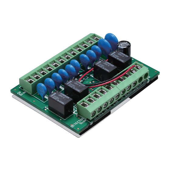
Power Convertor Unit
PCU-5
™
™
PARTS IDENTIFICATION
PCU-5 ×1, Putty ×2, Insulation Plate ×1
For the receiver, the step 2 & 3 are applied. For the transmitter, jump to the step 4.
2
Route connector cables (Alarm, Low battery
and Tamper, included in SL-100/200TNR) in
the back box through the hole to the battery box.
5
Adjust the wires so that they extend about
100 mm from the holes.
Fill the holes with the wires using the
supplied putty.
Control panel
8
Route the three connectors of the back box
through the slit on the upper part of the
main unit of the receiver. For the transmitter,
wire the two connectors in the same way.
INSTALLATION INSTRUCTIONS
Voltage convertor unit used to enable wired
operation of the detector.
SL-100/200TNR
For
The length of the wire
should be about 100 mm.
-1-
No.59-2069-1 1701-31
only
3
Connect the connector cable to the
terminals of PCU-5.
CP Side
Insert the insulation plate and PCU-5 as
6
illustrated. And then connect the wires to
the PCU-5 terminals.
Insulation sheet
Insert the PCU-5
board to the left side.
9
Attach the connectors.
Note>>
Put the cables in order not to be caught
between the main unit and cover.
Detector Side
Advertisement
Table of Contents

Related Manuals for Optex Smart Line PCU-5

Summary of Contents for Optex Smart Line PCU-5
- Page 1 No.59-2069-1 1701-31 INSTALLATION INSTRUCTIONS BATTERY OPERATED BATTERY OPERATED Power Convertor Unit Voltage convertor unit used to enable wired PCU-5 PHOTOELECTRIC DETECTOR PHOTOELECTRIC DETECTOR operation of the detector. Smart Line series Smart Line series ™ ™ SL-100/200TNR only OPTION OPTION PARTS IDENTIFICATION PCU-5 ×1, Putty ×2, Insulation Plate ×1 INSTALLATIONS For the receiver, the step 2 &...
- Page 2 SYSTEM DIAGRAM Transmitter Receiver Back box Main unit Back box Main unit Black Black Battery plate PCU-5 from PCU-5 PCU-5 Control panel PCU-5 Battery plate Power Power 10 - 30V – – Y ellow Alarm Alarm Orange * UNUSED Brown The DQ function is not provided UNUSED with the SL-TNR.
Need help?
Do you have a question about the Smart Line PCU-5 and is the answer not in the manual?
Questions and answers