Table of Contents
Advertisement
Quick Links
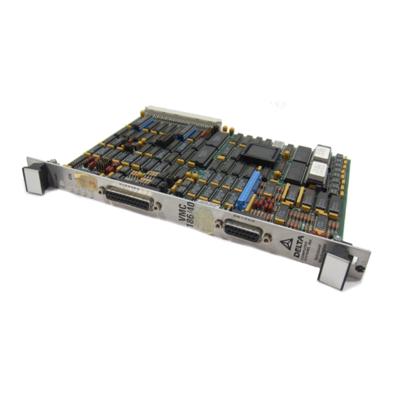
VMC 186/40
Motion Controller Module
931104
Delta Computer Systems, Inc. cannot be held responsible for the performance of any system in which the VMC
186/40 is used in a manner other than that for which it was originally intended, nor of any board which has
been modified by the owner.
Although great effort has been taken to ensure the accuracy of the information in this document, it is intended
to be used only as a guide. Knowledge of motion control, hydraulic servos, electric servos, magnetostrictive
transducers and safety rules is required. Delta Computer Systems, Inc. cannot accept responsibility for
problems resulting from omissions in this document.
Advertisement
Table of Contents

Related Manuals for Delta Computer Systems VMC 186/40

Summary of Contents for Delta Computer Systems VMC 186/40
- Page 1 931104 Delta Computer Systems, Inc. cannot be held responsible for the performance of any system in which the VMC 186/40 is used in a manner other than that for which it was originally intended, nor of any board which has been modified by the owner.
-
Page 2: Table Of Contents
Contents Overview ..............................4 Hardware Specifications..........................5 VME Memory Map ............................6 Motion Control Parameters ........................7 Read Only Parameters........................7 Command Position......................7 Target Position.......................7 Actual Position.......................7 Transducer Counts ......................7 Status Word ........................8 Bit Descriptions ......................8 Industrial Bus Status Word Bit Map................11 Drive ..........................12 Target Speed ........................12 Null Drive ........................12 Reserved Words......................12 Axis Setup Parameters .........................12... - Page 3 Initialization ..........................24 Position Sensing...........................24 Drive Output ..........................24 Closing the Loop..........................24 Integral and Differential Gains.....................25 Feed Forward ..........................25 Feed Forward Advance ........................26 Control at Rest ..........................26 Control Equations ........................26 Getting Started and Tuning the Axis ......................27 Step 1 - Setting Up the Initialization Parameters .................27 Direction Parameter .......................27 Scale Parameter......................27 Position Offset Parameter ....................28...
-
Page 4: Overview
The VMC 186/40 occupies one slot (two slots if options installed) of the VME rack. Programming of the VMC 186/40 is done using memory reads and writes. The on-board 80186 processor relieves the VME Controller of the overhead usually associated with servo control. -
Page 5: Hardware Specifications
VMC 186/40 Motion Control Module Overview Hardware Specifications VMC 186/40 12 MHz 80C186 processor Addressable 512 byte dual port RAM Bus interrupt for motion control errors or time interval iSBX connector for options (Serial I/F, Analog or Quadrature Options) One millisecond control loop time. -
Page 6: Vme Memory Map
VMC 186/40 Motion Control Module Memory Map VME Memory Map Memory Map Using Default Address Axis 1 0D0000H-0D007FH Axis 2 0D0080H-0D00FFH Axis 3 0D0100H-0D017FH Axis 4 0D0180H-0D01FFH Individual Axis Memory Map Hex Offset Parameter Name Default Value Descriptions Command Position... -
Page 7: Motion Control Parameters
VMC 186/40 Motion Control Module Control Parameters Motion Control Parameters The motion control parameters are the means of axis control. A complete understanding of the parameters and Status Word bits are necessary in order to fully utilize the motion controller's features. -
Page 8: Status Word
VMC 186/40 Motion Control Module Control Parameters Status Word The Status Word contains 16 bits of information about the axis. Five bits represent some type of motion error (Lag, Lead, Overdrive, Position Overflow, and Parameter Error) and can be used to trigger a halt or emergency stop. - Page 9 Note: If the VMC 186/40 is left on while the axis power is off or the drive output is disconnected, a Halt command should be issued to keep the null value from drifting.
- Page 10 VMC 186/40 Motion Control Module Control Parameters Bit 10 = Transducer Not Responding This bit will indicate when the transducer does not respond with valid data at least once every 10 milliseconds. The transducer data received is compared with previous data. If the two readings differ by more than 500 counts, the new reading is assumed to be an error.
-
Page 11: Industrial Bus Status Word Bit Map
VMC 186/40 Motion Control Module Control Parameters Industrial Bus Status Word Bit Map The axis Status Word contains 16 bits of information about the status of the axis. The hexadecimal table provides an easy method to convert bit patterns to hexadecimal numbers. -
Page 12: Drive
The Null Drive value is updated at intervals specified by the Null Update parameter. Reserved Words When the VMC 186/40 has the analog option installed, these memory location are used for additional parameters. Also, custom application programs may use these locations. -
Page 13: Estop Mask (Default: Ffffh Emergency Stop Disabled)
The bits in the Interrupt Mask are used to selectively enable interrupts. By clearing bit 12 of the mask, the VMC 186/40 can generate a overdrive error interrupt when an overdrive condition is detected. This word only needs to be used if the VME controller is configured to accept a bus interrupt. On start-up, this word is FFFFH. -
Page 14: Feed Forward Advance (Default: 0)
This reduces the variance between the measured position and actual position. Any variance may create control errors when the VMC 186/40 is used with a high speed target. If a value other than 0 is used, its range should be between 250 to 2000. The transducer position measurement will not be synchronized to the system clock, but will be free running. -
Page 15: Dither (Default: 0)
VMC 186/40 Motion Control Module Control Parameters Dither (Default: 0) The Dither value is the amplitude, in percent of full drive, of a 500 Hz square wave that is superimposed on the normal drive output. A value of 10 will cause a square wave of 10% of the drive to be applied on top of the normal output. -
Page 16: Differential Gain (Default: 0)
1. However, if one transducer count equals .0012 inches of physical travel, then a multiplier of 1.2 would be used. Since the VMC 186/40 only understands 16 bit unsigned integer numbers, 0 is used for a multiplier of 0, 32768 for a multiplier of 1 and 65535 for a multiplier of 1.999. - Page 17 0.001" and with one recirculation it is 0.002" or 0.05 mm. For more information on recirculation see page 33. Linear transducers have a calibration number (typically 9.1 µs per inch) and the VMC 186/40 has a 55.5 MHz oscillator for transducer position measurement counters. To determine the Scale for a magnetostrictive...
-
Page 18: Scale Calculation Examples
VMC 186/40 Motion Control Module Control Parameters Scale Calculation Examples Example 1 For a system using a magnetostrictive transducer with a calibration number of 9.1392, a position unit equal to one thousandths of an inch, and two recirculations, the Scale will be found as follows: 32768 Scale = ... -
Page 19: Direction (Default: 0) Possible Options: 0 And -1
Extend Limit (Defaults to actual position on reset) The Extend Limit specifies the maximum value that the VMC 186/40 will allow as a Command Position. (When Direction = -1 (65535), this is a minimum value.) Requested positions that exceed this value will be truncated. -
Page 20: Retract Limit (Defaults To Actual Position On Reset)
When set, this bit enables the axis simulator mode. In the simulator mode, the VMC 186/40 ignores the sensor inputs and sets the drive at null. When a 'G' command is given, the VMC 186/40 automatically copies the calculated target position into the actual position. This means the controller will execute a "perfect"... -
Page 21: Acceleration (Default: 1000)
VMC 186/40 Motion Control Module Control Parameters BIT 8 = Reserved Always have bit cleared. BIT 9 = Reserved Always have bit cleared. BIT 10 = Reserved Always have bit cleared. BIT 11 = Reserved Always have bit cleared. BIT 12 = Reserved Always have bit cleared. -
Page 22: Requested Position
The minimum requirement of this command is to set the Extend and Retract Limits to their proper values (see Getting Started on page 27). When a 'P' command is given, the VMC 186/40 will wait for a few milliseconds to get the actual position of the axis. This position is then copied into the Target and Command Position. - Page 23 VMC 186/40 Motion Control Module Control Parameters For example; if the operator wanted to produce 10% of full extend drive: (assumes current Null Drive value of 2048) Requested Speed 2047 (maximum valve drive) Requested Position 204 (10% of full positive drive)
-
Page 24: How It Works
If the actual position is ahead of the target position or leading, the VMC 186/40 will reduce the drive output to slow the axis down. The amount of drive for a given error in position is determined by three different proportional error gains: Static Gain, Extend Gain and Retract Gain. -
Page 25: Integral And Differential Gains
VMC 186/40 Motion Control Module How It Works when extending and retracting. Thus the difference between the actual and target positions can be reduced by increasing one of the three error gains. However, if a little bit of error gain is good, a lot is not always better. -
Page 26: Feed Forward Advance
Control at Rest When the VMC 186/40 is controlling the position of an axis at rest, it uses three parameters: Static Gain, Null Update and Differential Gain. Static Gain provides a drive output proportional to the error between the actual and target position. -
Page 27: Getting Started And Tuning The Axis
Step 1 - Setting Up the Initialization Parameters When the VMC 186/40 motion controller module is first turned on, default values are used for the initialization parameters. These values are there only to give the motion controller something to work with so the present position can be maintained. -
Page 28: Position Offset Parameter
Extend, and Retract) until the position can be moved without getting an error. Remember, the parameters are not updated in the VMC 186/40 until the 'P' command is issued. Lead errors can occur if the feed forward is too high or the axis response is too slow to respond to the output while ramping down. -
Page 29: Step 3 - Jogging The Axis
VMC 186/40 Motion Control Module Getting Started Step 3 - Jogging the Axis Jogging the axis can be accomplished by setting the Requested Position to the Extend or Retract Limit and using the 'G' and 'H' commands repeatedly. This causes the motion controller to Go and Halt. -
Page 30: Vme Controller Programming Precautions
VME Controller Error Handling The VMC 186/40 reports errors within a millisecond. This is done by setting a bit in the axis Status Word and flashing the appropriate Front Panel LED. The VME Controller is responsible for checking errors using the Status Word. -
Page 31: Front Panel Indicators
Hardware Information Front Panel Indicators There are five multicolored light emitting diodes (LED) on the front panel of the VMC 186/40. The LED's provide status information about each axis. The LED labeled Run is the run indicator of the VMC 186/40 microprocessor. When the Run indicator is green, the drive outputs are enabled. -
Page 32: Hardware Configuration Information
P8-P11 Select number of transducer recirculations (page 33) Enable a VMC 186/40 module reset if the module fails to toggle a 60 ms timer (page 36) Enable on-board interrupt if the module fails to toggle a 13 ms timer (page 36) -
Page 33: Magnetostrictive Transducer Interrogation Pulse Polarity
We recommend ordering only positive interrogation pulse for system consistency. Note: If the VMC 186/40 is connected to a negative interrogation pulse transducer when it is configured for positive interrogation pulses, current limiting resistors on the VMC 186/40 will burn out. The current limiting resistors protect the transducer rod and are field replaceable. - Page 34 CAUTION: The longest measurement time should never exceed 1000 microseconds. The data used by the VMC 186/40 must be available within its millisecond control loop for precise control. If more than 1000 microseconds is required to obtain a position measurement, the controller will slow down to a two millisecond control loop.
-
Page 35: Dual Port Address Selection
Jumpers P15-P16 (Default for 0D0000H) Jumpers P15-P16 are used to set the VME bus address of the dual port memory of the VMC 186/40. The jumpers allow the dual port memory to be placed anywhere in the 16 megabyte address space. The upper 15 address lines are used to select the dual port RAM which always starts on a 512 byte boundary. -
Page 36: Fail Safe Timer Operation
This allows the VME Controller to reset the VMC 186/40. When Sysreset is active and P14 is installed, the VMC 186/40 processor is held in the reset state. When the VMC 186/40 is held in the reset state, the 12us time-out will disable the drive circuits. -
Page 37: Vme Bus Interrupt Selection
Note: Both P17 and P18 must be changed if a different IRQ is used The VMC 186/40 is an ROAK interrupter (Release On Acknowledge - the interrupt is released on reading the status/ID). When the VMC 186/40 generates an interrupt on the selected IRQ line (jumper P17 selected), it will respond to an 8 bit, 16 bit, or 32 bit interrupt acknowledge cycle by providing an 8 bit status/ID on D00-D07. -
Page 38: Drive Selection
An external resistor network can be used to scale the 100mA output to a lower full scale current. This allows the maximum output resolution of the VMC 186/40 board to be utilized with valves of less than full scale output. Use of the network will also help to prevent damage to the controller board from excessive power dissipation. -
Page 39: External Wiring And Site Installation Information
External Wiring and Site Installation Information The VMC 186/40 can be placed in any VME chassis slot. External power supplies must be provided for both the transducer inputs and drive outputs. The power supplies should supply +5 volts and ± 15 volts with at least 500 mA. - Page 40 VMC 186/40 Motion Hardware Information Typical Temposonics Connector MS310614A-P Function Color Connector +12 to +15V Green DC Common Black Return Pulse Orange -13.5 to -15V Blue Interrogation Pulse White +11.5 to +12V The cable provided with module to connect the application's drive inputs to the DB15 front panel connector...
-
Page 41: Common Problems And Solutions
Terminate the shield at module end, or transducer end or both. d. Install a pair of Delta Computer Systems, Inc. AMP/10 RS-422 converter cards. If a TEMPO II transducer is used, the RPM option along with one AMP/10 card is recommended. See attached wiring diagrams. -
Page 42: Repairs And Returns
2). If interrogation pulse failure, change pulse drivers U10 and U11 (SN75158P) Module Returns When returning the VMC 186/40 for repair, please contact Delta prior to shipment for an RMA number. Returned modules should be packaged in static protection material and the RMA number clearly marked on the outside of package. -
Page 43: Glossary
Moving or turning the axis such that the transducer counts decrease. A generic name for a type of circuit board with specific electrical and physical specifications. One SBX connector is provided on the VMC 186/40 board. Scale A multiplier used to translate transducer counts to position units. It can be used as a means of compensation for differences in magnetostrictive transducers. -
Page 44: Ascii Code Chart
VMC 188/40 Motion Controller Appendix A ASCII Code Chart Code Mnem Code Code Code Ctrl A Ctrl B " Ctrl C Ctrl D Ctrl E Ctrl F & Ctrl G Ctrl H Ctrl I Ctrl J Ctrl K Ctrl L Ctrl M Ctrl N Ctrl O... -
Page 45: External Wiring Examples
VMC 186/40 Motion Controller Appendix B External Wiring Examples ...
Need help?
Do you have a question about the VMC 186/40 and is the answer not in the manual?
Questions and answers