L-Acoustics KS21i Owner's Manual
Hide thumbs
Also See for KS21i:
- Owner's manual (119 pages) ,
- Owner's manual (100 pages) ,
- Owner's manual (82 pages)
Table of Contents
Advertisement
Quick Links
Advertisement
Table of Contents

Related Manuals for L-Acoustics KS21i


Summary of Contents for L-Acoustics KS21i
- Page 1 KS21i owner's manual (EN)
- Page 2 Document reference: KS21i owner's manual (EN) version 1.0 Distribution date: September 1, 2020 © 2020 L-Acoustics. All rights reserved. No part of this publication may be reproduced or transmitted in any form or by any means without the express written consent of the publisher.
-
Page 3: Table Of Contents
A15i-BUMP...........................13 A-U15i............................15 Ai-FIXBRACKET..........................17 Front screens............................18 Mechanical safety.............................20 Loudspeaker congurations..........................22 KS21i in standard conguration.......................22 KS21i in cardioid conguration....................... 23 Rigging procedures............................24 General principles...........................24 Tools..............................26 Flying..............................27 Flying a vertical array with A15i-BUMP..................27 Wall-mounting or ceiling-mounting......................31 Mounting an assembly with A-U15i....................31 Mounting an assembly on a ceiling with Ai-FIXBRACKET.............. - Page 4 Connection to LA amplied controllers........................ 45 Cabling..............................47 Specications..............................50 APPENDIX A: Congurations with A-U15i......................54 APPENDIX B: Recommendation for speaker cables....................56 APPENDIX C: Specications for custom rigging systems..................57...
-
Page 5: Safety
Respect the Working Load Limit (WLL) of third party equipment. L-Acoustics is not responsible for any rigging equipment and accessories provided by third party manufacturers. Verify that the Working Load Limit (WLL) of the suspension points, chain hoists and all additional hardware rigging accessories is respected. - Page 6 This system is intended for use by trained personnel for professional applications. As part of a continuous evolution of techniques and standards, L-Acoustics reserves the right to change the specications of its products and the content of its documents without prior notice.
-
Page 7: Introduction
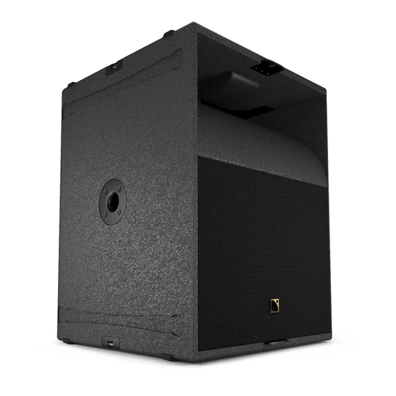
KS21i features one high excursion, direct-radiating 21'' transducer mounted in a bass-reex tuned enclosure. KS21i couples with A15i and A10i to reinforce contour and extend bandwidth to 29 Hz and 31 Hz respectively. KS21i features L-Vents that substantially reduce turbulence and port noise at high levels while also increasing LF efciency. -
Page 8: System Components
Refer to the LA2Xi / LA4X / LA8 / LA12X owner's manual for detailed instructions about the whole cabling scheme, including modulation cables and network. Rigging elements A15i-BUMP Flying frame for vertical deployment of A15i and KS21i A-U15i U-bracket for A15i and KS21i Ai-FIXBRACKET... -
Page 9: Loudspeaker Cables
A15i-BUMP A-U15i KS21i-SCREEN Rigging plates KS21i-LINK KS21i- KS21i-ULINK ENDLINK FIXBRACKET Rigging plates Rigging plates for KS21i End rigging Fastening for ying plates for brackets for two KS21i KS21i KS21i, A10i with A-U15i and KS21i KS21i owner's manual (EN) version 1.0... -
Page 10: Electro-Acoustical Description
Each set of terminal block connectors (+ and −) can be used interchangeably as IN or LINK connector. KS21i 1 × 4-point terminal block with push-in connection Internal pinout for L-Acoustics subwoofers terminal block points IN + IN - Transducer connectors LF + LF - KS21i owner's manual (EN) version 1.0... -
Page 11: Rigging System Description
Rigging system description Rigging system description KS21i KS21i is compatible with four types of rigging plate kits: • standard rigging plates • S-shaped standard rigging plates (KS21i-LINK) (KS21i-SLINK) • end rigging plates • S-shaped end rigging plates (KS21i-ENDLINK) (KS21i-ENDSLINK) KS21i features 18 inserts on each side: •... - Page 12 Rigging system description Rigging screws Only use the rigging screws provided by L-Acoustics. Do not use the placeholder screws for rigging. Always put the placeholder screws back in place to avoid leaks. KS21i owner's manual (EN) version 1.0...
-
Page 13: Rigging Elements
Rigging elements A15i-BUMP A15i-BUMP is a reversible rigging frame for ying vertical arrays of KS21i. A15i-BUMP is secured to the array with four M6x18 rigging screws and M6 nuts (provided). Multiple pickup points are available for site angle adjustments: 16 pickup points on each side, one front pickup point (F), and one rear pickup point (R). - Page 14 Rigging system description A15i-BUMP can be used as the main lifting accessory for ying vertical arrays of KS21i with one or two lifting points. KS21i owner's manual (EN) version 1.0...
-
Page 15: A-U15I
Rigging system description A-U15i A-U15i is a U-bracket for mounting KS21i on a ceiling, a wall, or a truss. In combination with KS21i-ULINK, A-U15i can be used to mount or y vertical arrays of two KS21i. KS21i owner's manual (EN) version 1.0... - Page 16 WITH SOUNDVISION SOFTWARE. A-U15i must be secured to the supporting xture with four M10 screws or a truss clamp. Fasteners for wall-mounting or ceiling-mounting Select screw length and anchors applicable to the wall or ceiling properties. KS21i owner's manual (EN) version 1.0...
-
Page 17: Ai-Fixbracket
Rigging system description Ai-FIXBRACKET Ai-FIXBRACKET is a set of four fastening brackets for KS21i. The enclosure is secured to Ai-FIXBRACKET using the slotted hole. Secure Ai-FIXBRACKET at the bottom of an array to improve stability. Ai-FIXBRACKET can also be used to mount up to two KS21i under the ceiling. -
Page 18: Front Screens
Rigging system description Front screens The KS21i system features an acoustically transparent front screen suitable for every conguration. The screens are secured on top of the rigging plates with four M6 rigging screws: • Two M6x20 screws on the vent side. - Page 19 The screws of the grill and the placeholder screws on the ns side can be removed through the rigging plates. The screens are equipped with tabs to hold the grill in place when securing the screen on the enclosure. KS21i-SCREEN can be secured to the back of KS21i when used in cardioid conguration. KS21i owner's manual (EN) version 1.0...
-
Page 20: Mechanical Safety
Mechanical safety Mechanical safety Flown congurations The KS21i rigging system complies with 2006/42/EC: Machinery Directive. It has been designed following the guidelines of BGV-C1. 2006/42/EC: Machinery Directive species a safety factor of 4 against the rupture. The own deployments described in this manual achieve a safety factor of 4 or more. - Page 21 Soundvision calculations are based on usual environmental conditions. A higher safety factor is recommended with factors such as extreme high or low temperatures, strong wind, prolonged exposition to salt water, etc. Always consult a rigging specialist to adopt safety practices adapted to such a situation. KS21i owner's manual (EN) version 1.0...
-
Page 22: Loudspeaker ConGurations
Loudspeaker congurations KS21i in standard conguration Deployed in a standard conguration, a KS21i system operates with an omnidirectional directivity pattern over the nominal bandwidth of the KS21i enclosure. The [KS21_60] and [KS21_100] factory presets provide the subwoofer system with an upper frequency limit at 60 Hz and 100 Hz respectively in order to optimize the acoustic coupling with a main full-range system. -
Page 23: Ks21I In Cardioid ConGuration
KS21i in cardioid conguration Deployed in a cardioid conguration, a KS21i system produces a rear SPL rejection. The deployment consists of an array of four KS21i with one element turned towards the rear (reversed). Refer to the Cardioid Conguration technical bulletin for more information. -
Page 24: Rigging Procedures
Securing rigging plates on an enclosure • Make sure that the inserts for the screens are accessible. Driving screws Do not fully tighten the screws unless otherwise instructed. Follow the indicated torque when tightening a screw. KS21i owner's manual (EN) version 1.0... - Page 25 Securing rigging plates between two enclosures • Always secure standard rigging plates with the linking section upwards. • After securing an enclosure to another enclosure, tighten all the screws on the supporting enclosure. 5 N.m KS21i owner's manual (EN) version 1.0...
-
Page 26: Tools
Other manufacturers can be used. Name Reference Distributor Set of 6-point 1/4" sockets RL.NANO1 / R.360NANO FACOM electric screwdriver with torque selector Torque screwdriver (2 - 10 N.m) A.404 FACOM 10 mm wrench KS21i owner's manual (EN) version 1.0... -
Page 27: Flying
KS21i-LINK Rigging plates for KS21i Risk of falling objects Verify that no unattached items remain on the product or assembly. Secondary safety Use available holes on the rigging accessories to implement a secondary safety. KS21i owner's manual (EN) version 1.0... - Page 28 1. Prepare the enclosures by removing the placeholder screws and securing rigging plates on both sides. KS21i 2. Secure A15i-BUMP on top of KS21i. 3. Select the pick-up point and raise the array. 9 10 11 12 13 14 15 16...
- Page 29 Hold the enclosure at the bottom until the rigging plates are secured. Lift the rear of the new KS21i and secure it to the array by pre-tightening a rigging screw on both sides. b) Remove the rigging screws at the bottom front on both sides of the supporting KS21i.
- Page 30 Rigging procedures e) Repeat the procedure until the KS21i array is completed. 5. Check that all the screws are secured and tightened (5 N.m torque) and raise the array. What to do next Securing a screen (p.43) KS21i owner's manual (EN) version 1.0...
-
Page 31: Wall-Mounting Or Ceiling-Mounting
A-U15i in horizontal position, with 1 enclosure 275 daN 65 daN Wall-mounted A-U15i in horizontal position, with 2 enclosures 375 daN 75 daN A-U15i in vertical position, with 1 enclosure 40 daN 30 daN Ceiling-mounted 150 daN — KS21i owner's manual (EN) version 1.0... - Page 32 120 mm / 4.7 in Ø M10 (x4) 2. Prepare a KS21i by removing the placeholder screws at the center of each side of the enclosure. 3. Using the screws provided with A-U15i, drive a screw on both sides. Approximately 10 mm (0.4 in) of the thread must be visible.
- Page 33 5. Set the angle: For a single enclosure: a. Rotate the enclosure to align the second insert with the selected site angle. b. Drive a screw on both sides. c. Tighten all the screws (5 N.m torque). KS21i owner's manual (EN) version 1.0...
- Page 34 Slide the KS21i-ULINK rigging plates between A-U15i and the enclosure, with the hooks facing front. b. Rotate the enclosure and the rigging plates to align the second insert and the rigging plates with the selected site angle.
- Page 35 Rigging procedures 6. Prepare a new KS21i by removing the two placeholder screws at the center of each side of the enclosure. 7. Secure the enclosure to the U-bracket rigging plates. Apply a torque of 5 N.m. If the two enclosures are misaligned at the front, loosen the screws on the U-rigging plates and realign the two enclosures, then re-tighten the screws.
-
Page 36: Mounting An Assembly On A Ceiling With Ai-Fixbracket
In a ceiling-mounted conguration, the array applies a force of 60 daN on the anchoring points. Assembly Procedure 1. Secure Ai-FIXBRACKET to the ceiling using M10 screws. Fasteners for wall-mounting or ceiling-mounting Select screw length and anchors applicable to the wall or ceiling properties. 828 mm / 32.6 in KS21i owner's manual (EN) version 1.0... - Page 37 2. Prepare an enclosure by removing the placeholder screws and securing end rigging plates on both sides. 3. Secure the rear of the enclosure to Ai-FIXBRACKET. 4. Lift the front of the enclosure and secure it to Ai-FIXBRACKET. 5. Tighten the screws on Ai-FIXBRACKET (5 N.m torque). KS21i owner's manual (EN) version 1.0...
- Page 38 7. Remove the bottom screws of the supporting enclosure. 8. Link the two enclosures at the rear by pre-tightening a rigging screw on both sides. This step requires three operators. Hold the enclosure at the bottom until the rigging plates are secured. KS21i owner's manual (EN) version 1.0...
- Page 39 9. Link the two enclosures at the front by pre-tightening a rigging screw on both sides. 10. Check that all the screws are secured and tightened (5 N.m torque). What to do next Securing a screen (p.43) KS21i owner's manual (EN) version 1.0...
-
Page 40: Stacking
Always secure a stacked array to the ground using Ai-FIXBRACKET to ensure stability of the array. Ai-FIXBRACKET in stacked conguration In a stacked conguration, the array applies a force of 110 daN on the anchoring points. KS21i owner's manual (EN) version 1.0... - Page 41 Rigging procedures Assembly Procedure 1. Prepare a KS21i by removing the placeholder screws and securing rigging plates on both sides. 2. Secure Ai-FIXBRACKET to the ground using M10 screws. Fasteners for wall-mounting or ceiling-mounting Select screw length and anchors applicable to the wall or ceiling properties.
- Page 42 Rigging procedures 4. Secure up to three additional KS21i on top of the rst one. For the last KS21i, use KS21i-ENDLINK. Tighten all the screws on the previous enclosure after securing each new enclosure. What to do next Securing a screen (p.43)
-
Page 43: Securing A Screen
About this task Procedure 1. Remove the placeholder screws on the ns side and the grill screws from the inserts. 2. Secure the screen using the provided rigging screws. Apply a torque of 5 N.m. KS21i owner's manual (EN) version 1.0... - Page 44 Risk of bending screen xing tabs Always use the self-sticking washers for securing screens when there are no rigging plates on the enclosure. Secure the screen to the back of KS21i when used in cardioid conguration. KS21i owner's manual (EN) version 1.0...
-
Page 45: Connection To La AmpliEd Controllers
LA8 can drive up to two KS21 or KS21i per output, but no more than six per controller at high level. KS21i owner's manual (EN) version 1.0... - Page 46 Connection to LA amplied controllers Cabling schemes for KS21i (LA4X / LA8 / LA12X) Refer to the cabling schemes to connect the enclosures to different types of output congurations. One-channel speakON output custom speakON 2.5 mm² cable 1+/1- Two-channel speakON output...
-
Page 47: Cabling
Min number of operators Assembly Prerequisite APPENDIX B: Recommendation for speaker cables (p.56). Procedure 1. On the connector sealing plate, remove the sealing nut from the cable gland. 2. Insert the cable in the sealing nut. KS21i owner's manual (EN) version 1.0... - Page 48 3. Insert the cable in the cable gland. 4. Strip the wires of the cable. 30 mm 10 mm 5. Secure the wires in the connectors. Use a small tool to unlock the connectors. KS21i owner's manual (EN) version 1.0...
- Page 49 6. Secure the connector sealing plate to the connector plate. 3 N.m 7. Tighten the sealing nut. What to do next To connect a second enclosure in parallel, remove the protective plug from the second cable gland and repeat the procedure. KS21i owner's manual (EN) version 1.0...
-
Page 50: SpeciCations
Pantone 426 C pure white RAL 9010 custom RAL code on special order IP55 Peak level at 1 m under half space conditions using pink noise with crest factor 4 (preset specied in brackets). KS21i owner's manual (EN) version 1.0... - Page 51 Specications KS21i dimensions 752 mm / 29.6 in 602 mm / 23.7 in KS21i owner's manual (EN) version 1.0...
- Page 52 Specications A15i-BUMP specications Description Flying frame for vertical deployment of A15i and KS21i Weight (net) 16 kg / 35 lb Material high grade steel with anti-corrosion coating A15i-BUMP dimensions 656 mm / 25.8 in 600 mm / 23.6 in 758 mm / 29.8 in...
- Page 53 U-bracket for A15i and KS21i Weight (net) 4.9 kg / 11 lb Material high grade steel with anti-corrosion coating A-U15i dimensions 150 mm / 5.9 in 823 mm / 32.4 in 135 mm / 5.3 in KS21i owner's manual (EN) version 1.0...
-
Page 54: Appendix A: ConGurations With A-U15I
A+B (center 0° (site) -5° / +5° 10° screw) -90° (site) -20° / +20° 10° 0° / +20° (wall)* 0° (site) 10° -20° / +20° (pillar) 0° (wall)* 0° (site) 10° -20° / +20° (pillar) KS21i owner's manual (EN) version 1.0... - Page 55 (-30° to 0° (azimuth) 10° +30°) A+B -20° / +20° (pillar) * The cables and connectors at the back of KS21i limit the range of possible site or azimuth angles when the assembly is wall-mounted. KS21i owner's manual (EN) version 1.0...
-
Page 56: Appendix B: Recommendation For Speaker Cables
8 Ω load 4 Ω load 2.7 Ω load Use the more detailed L-Acoustics calculation tool to evaluate cable length and gauge based on the type and number of enclosures connected. The calculation tool is available on our website: https://www.l-acoustics.com/en/installation/tools/... -
Page 57: Appendix C: SpeciCations For Custom Rigging Systems
• Prevent screws from loosening (threadlocker, spring washer...). Threaded inserts • Ultimate Tensile Strength: 1160 N • Ultimate Shear Strength: 5370 N • Recommended torque: 5 N.m for M6 inserts, 7 N.m for M8 inserts KS21i owner's manual (EN) version 1.0... - Page 58 L-Acoustics 13 rue Levacher Cintrat - 91460 Marcoussis - France +33 1 69 63 69 63 - info@l-acoustics.com www.l-acoustics.com...
Need help?
Do you have a question about the KS21i and is the answer not in the manual?
Questions and answers