Table of Contents
Advertisement
DIESEL SPACE HEATER - SERVICE MANUAL
1. CONTROLS AND COMPONENTS
2. FLAME CONTROL CYCLES
3. MAINTENANCE SCHEDULE
4. REPAIR PROCEDURES
1. FAN MOTOR ASSEMBLY
2. FUEL FILTER ASSEMBLY
3. FUEL PUMP ASSEMBLY
4. ELECTRIC PANEL ASSEMBLY
5. AIR PRESSURE SWITCH
6. COMBUSTION HEAD ASSEMBLY
7. COMBUSTION CHAMBER
8. COMBUSTION TEST
5. TROUBLESHOOTING GUIDE
6. WIRING DIAGRAMS
7. TECHNICAL SHEETS
GE 360 – GE 400 – GE 600
The operations described in this booklet must be carried out by qualified and instructed personnel
Incorrect maintenance may result in improper operation and serious injury.
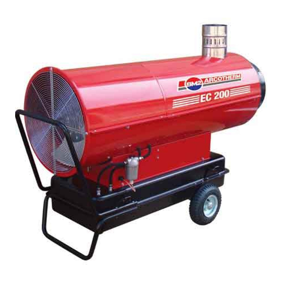
EC 200 – EC 300
WARNING
INDEX
1
L-S 102.00-BM
only.
Advertisement
Table of Contents

Subscribe to Our Youtube Channel
Related Manuals for Arcotherm EC 200


Summary of Contents for Arcotherm EC 200
- Page 1 8. COMBUSTION TEST 5. TROUBLESHOOTING GUIDE 6. WIRING DIAGRAMS 7. TECHNICAL SHEETS EC 200 – EC 300 GE 360 – GE 400 – GE 600 L-S 102.00-BM WARNING The operations described in this booklet must be carried out by qualified and instructed personnel only.
-
Page 2: Controls And Components
1. CONTROLS AND COMPONENTS :EC 200 – EC 300 NDIRECT HEATER WITH STACK 1 COMBUSTION CHAMBER 2 BURNER ASSEMBLY 3 NOZZLE 4 FUEL VALVE 5 DIESEL PUMP 6 MOTOR 7 FAN 8 FUEL FILTER 9 FUEL CIRCUIT 10 FUEL TANK... - Page 3 CONTROL SYSTEM The heater has all operational controls located in a watertight control panel mounted on the lateral side of the unit. The control panel consists of: • a 3-position switch for heating function: normal operation, stop or thermostat operation •...
-
Page 4: Starting Cycle
2. FLAME CONTROL RUNNING / FAILURE CYCLE 2.1 S TARTING CYCLE The flame control unit starts the sequence of operation after a heating request (normal operation or thermostat operation) and it consists of the following steps: • Self-test (less than 3 s): self-check of electronics efficiency; •... - Page 5 2.3 F LAME FAILURE DURING STARTING CYCLE If during the safety time TS, the photocell monitors a flame failure (signal to photocell become lower than minimum), at the end of safety time the unit goes in lock out condititon: • burner fan, ignition transformer and fuel valve are de-energized;...
- Page 6 2.5 F LAME FAILURE DURING RUNNING STATUS ONE TRIAL RECYCLING In case of flame failure in running status, the flame control unit make one trial restarting the unit. If the reason of flame failure is confirmed, then the unit stops in lock-out mode, and the reset lamp becomes red. 2.6 R ESET LAMP COLOR WARNING...
-
Page 7: Maintenance Schedule
3. MAINTENANCE SCHEDULE Periodic maintenance of the heater is necessary to ensure proper performance and to prevent failures and it shall be performed at the following periodic intervals: • Daily maintenance i. Inspect air inlet / air outlet and exhaust stack, remove debris if any ii. -
Page 8: Repair Procedures
4. REPAIR PROCEDURES WARNING Before carrying out any maintenance operation the heater must be disconnected from power supply. Refer to instruction manual to fully stop the heater. Therefore: • Stop the machine as instructed • Turn off the disconnecting switch on the main electric switchboard •... - Page 9 b) To replace the fan blade and the electric motor, carry out the following procedure. Remove the air inlet grille (a) by removing four screws that secure it to the machine. ii) Loosen the screw (d) on the fan hub iii) Extract the fan blades and replace with a new one respecting blades orientation iv) Remove the top cover access panel (b) by removing four screws v) Loosen three screws (e) on the fuel pump casing (be sure not to remove the screws)
-
Page 10: Fuel Filter Assembly
2) FUEL FILTER ASSEMBLY a) To clean / replace the pre-heated type fuel filter, carry out the following procedure. Remove the screw (a) that secures the cover to the housing and remove o-ring (b) ii) Using a suitable container, collect the fuel when removing from the fuel filter assembly iii) Remove the fuel cell (c) and wash it with clean diesel oil iv) If necessary replace the fuel cell (c) v) If necessary to replace the heating element, loosen the nut (d) and remove the electric resistance (e) -
Page 11: Fuel Pump Assembly
b) To clean / replace the standard type fuel filter, carry out the following procedure. Loosen the casing (a) that secures to the housing ii) Using a suitable container, collect the fuel when removing from the fuel filter assembly iii) Remove fuel cell (c) and o-ring (b) and wash with clean diesel oil iv) If necessary replace the fuel cell (c) v) Inspect the o-ring, replace it if it is cracked, damaged, or deformed vi) Reassemble the filter assembly checking the o-ring is placed in the right position... -
Page 12: Electric Panel Assembly
b) To set fuel pressure on fuel pump, carry out the following procedure. Remove the top cover access panel (b) by removing six screws ii) Loosen cap (a) on front of fuel pump and connect a fuel pressure meter iii) Disconnect wires lead to fuel solenoid valve (to avoid fuel spray inside combustion chamber) WARNING The following operation shall be done with top cover and possible access to rotating fan. -
Page 13: Air Pressure Switch
iii) Check that all connections are complete and tight iv) Reassemble top cover (b) and fix electric board to the heater 5) AIR PRESSURE SWITCH a) To check / replace air pressure switch, carry out the following procedure. Remove four screws (a) on side of heater ii) Pull air pressure switch assembly out of the base iii) Check silicon tube are not pinched and tightened to connectors iv) Check there is no debris inside silicon tube... - Page 14 iii) Turn counterclockwise burner support (d) and pull it out of burner tube (e) iv) Check / Clean diffuser ring (f) (1) be sure any debris or soot is eliminated every wing and opening on front surface of ring (2) if necessary loosen screw (f) and remove it to wash using clean diesel (3) check for any damage or bended part: if any replace it v) Check / clean ignition electrodes (g) (1) Clean and remove any debris or soot on sharp ends of electrodes...
- Page 15 vi) Check/replace fuel nozzle (1) Refer to technical data sheet for specific indication of nozzle type (2) Remove electrodes (g) (3) Remove diffuser ring (f) (4) Loosen fuel nozzle and place a new one (5) Reassemble diffuser ring and electrodes taking care of each correct positioning as by previous instructions vii) Check / clean photocell (1) Remove photocell (i) and check it is clean...
-
Page 16: Combustion Chamber Assembly
ix) Reassemble combustion head x) Reassemble top cover 7) COMBUSTION CHAMBER ASSEMBLY a) To clean combustion chamber assembly, carry out the following procedure. Remove the top cover access panel (b) by removing six screws ii) Loosen and remove three nuts (a) iii) Remove the burner head tube assembly (c) iv) Check and clean inside combustion chamber with a cloth, removing liquid fuel residual v) Reassemble burner head tube assembly (c) - Page 17 8) COMBUSTION TEST (HEATER WITH FLUE ONLY) a) To check combustion smoke index with Shell-Bacharach method, carry out the following procedure. Use a standard Bacharach pump (a). ii) Insert a test strip (b) into the pump slot. iii) Insert the pump end into the flue connection (c) or flue extension. iv) Start the heater and wait five minutes until it operates in standard conditions v) Pump in exhaust gases for 10 times, taking care to carry out all movements slowly and using the complete piston stroke.
-
Page 18: Troubleshooting Guide
5. TROUBLESHOOTING GUIDE A. H EATERS DOES NOT START a. Main control lamp is off i. Missing connection to main supply line Check main supply is switched on Check connection of extension power cord Check integrity of main fuse b. Motor does not run and reset lamp is red i. - Page 19 C. H EATER STARTS BUT IT DOES NOT RUN REGULARLY a. Heater stops in lock-out and reset lamp is on (red light) i. Flame failure because of missing fuel Check fuel tank not be empty Check fuel type be correct, clean without water Check and clean fuel filter cartridge Check all connections of fuel line from tank to fuel pump: untightened connections can cause suction of air to fuel pump...
- Page 20 E. W HEN SWITCHING OFF HEATER DOES NOT STOP a. Heater still runs with flame i. Room thermostat / main switch failure Check room thermostat and room thermostat connections Check main switch on heater control board ii. Fuel flow to nozzle is not interrupted Check fuel solenoid valve is closing fuel line to nozzle...
-
Page 21: Wiring Diagram
6. WIRING DIAGRAM EC 200 – EC 300 – GE 360 – GE 400 Fuse 20 A Main switch H.T. Transformer Room thermostat plug Overheat thermostat Flame control box Fuel solenoid valve Heated fuel filter (optional) Photocell Air pressure switch... - Page 22 GE 600 Fuse 20 A Main switch H.T. Transformer Room thermostat plug Overheat thermostat Flame control box Fuel solenoid valve Heated fuel filter (optional) Photocell Air pressure switch Capacitor Fuse 6,3 A Fan motor RELAY Control lamp FUSE 20 A NOTE Air pressure switch PA and overheating thermostat LI1 are connected in serie to fuel valve EV1.
-
Page 23: Technical Specification
7. TECHNICAL SPECIFICATION TECHNICAL SPECIFICATIONS EC 200 EC 300 GE 360 GE 400 GE 600 Heat input [kBTU/h] 204.873 293.982 361.439 396.376 599.524 Air flow 1,530 2,531 1.795 2.500 2.800 [cfm] Heat output [kBTU/h] 183.362 258.704 Fuel consumption 1.48 2.17 2.60...
Need help?
Do you have a question about the EC 200 and is the answer not in the manual?
Questions and answers