Table of Contents
Advertisement
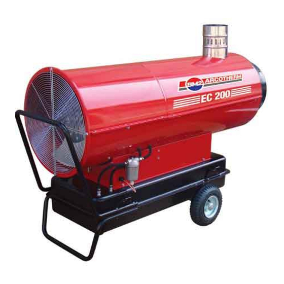
DIESEL SPACE HEATER - SERVICE MANUAL
1. CONTROLS AND COMPONENTS
2. FLAME CONTROL CYCLES
3. MAINTENANCE SCHEDULE
4. TROUBLESHOOTING GUIDE
5. REPAIR PROCEDURES
1. FAN MOTOR ASSEMBLY
2. FUEL FILTER ASSEMBLY
3. FUEL PUMP ASSEMBLY
4. ELECTRIC PANEL ASSEMBLY
5. AIR PRESSURE SWITCH
6. COMBUSTION HEAD ASSEMBLY
7. COMBUSTION CHAMBER
8. COMBUSTION TEST
6. WIRING DIAGRAMS
7. TECHNICAL SHEETS
GE 360 – GE 400 – GE 600
The operations described in this booklet must be carried out by qualified and instructed personnel
Incorrect maintenance may result in improper operation and serious injury.
EC 200 – EC 300
WARNING
INDEX
1
L-S 102.01-BM
only.
Advertisement
Table of Contents

Subscribe to Our Youtube Channel
Related Manuals for Arcotherm EC 200


Summary of Contents for Arcotherm EC 200
- Page 1 7. COMBUSTION CHAMBER 8. COMBUSTION TEST 6. WIRING DIAGRAMS 7. TECHNICAL SHEETS EC 200 – EC 300 GE 360 – GE 400 – GE 600 L-S 102.01-BM WARNING The operations described in this booklet must be carried out by qualified and instructed personnel only.
-
Page 2: Controls And Components
1. CONTROLS AND COMPONENTS :EC 200 – EC 300 NDIRECT HEATER WITH STACK 1 COMBUSTION CHAMBER 2 BURNER ASSEMBLY 3 NOZZLE 4 FUEL VALVE 5 DIESEL PUMP 6 MOTOR 7 FAN 8 FUEL FILTER 9 FUEL CIRCUIT 10 FUEL TANK... - Page 3 CONTROL SYSTEM The heater has all operational controls located in a watertight control panel mounted on the lateral side of the unit. The control panel consists of: a 3-position switch for heating function: normal operation, stop or thermostat operation ...
-
Page 4: Operating Cycles
2. FLAME CONTROL CYCLES 2.1 R ESET LAMP LIGHT During the operating condition, the reset button may have different type of light depending of its operating status (FUNCTION LIGHT): • flashing green: unit is in stand-by status, waiting for heating request. •... - Page 5 Self-test (less than 3 s): self-check of electronics efficiency; Purging time T (20 seconds): fan motor and ignition transformer are simultaneously switched on while the fuel valve remains closed to eliminate any fuel or unburnt residual. During the purging stage, the flame signal is constantly monitored and any kind of failure leading to combustion prevents the burner ignition causing the controls to lock out the unit.
- Page 6 burner fan, ignition transformer and fuel valve are de-energized; alarm lamp on reset button becomes steady red If troubleshooting on reset button is activated as described in 2.1, then the alarm lamp on reset button starts flashing with 2 blinks. FUNCTION LIGHT: steady red SELF-DIAGNOSIS LIGHT: flashing red with 2 blinks Unit can re-start only after pressing the reset button.
- Page 7 If troubleshooting on reset button is activated as described in 2.1, then the alarm lamp on reset button starts flashing with 7 blinks. FUNCTION LIGHT: steady red SELF-DIAGNOSIS LIGHT: flashing red with 7 blinks Unit can re-start only after pressing the reset button.
-
Page 8: Maintenance Schedule
3. MAINTENANCE SCHEDULE Periodic maintenance of the heater is necessary to ensure proper performance and to prevent failures and it shall be performed at the following periodic intervals: Daily maintenance i. Inspect air inlet / air outlet and exhaust stack, remove debris if any ii. -
Page 9: Troubleshooting Guide
4. TROUBLESHOOTING GUIDE PROBLEM RESET BUTTON (13) CAUSE REMEDY • Check mains • Check proper positioning and functioning of • No electrical current switch • Motor does not start, no • Check fuse ignition • Check correct setting of heater control. If •... -
Page 10: Repair Procedures
5. REPAIR PROCEDURES WARNING Before carrying out any maintenance operation the heater must be disconnected from power supply. Refer to instruction manual to fully stop the heater. Therefore: • Stop the machine as instructed • Turn off the disconnecting switch on the main electric switchboard •... - Page 11 b) To replace the fan blade and the electric motor, carry out the following procedure. Remove the air inlet grille (a) by removing four screws that secure it to the machine. ii) Loosen the screw (d) on the fan hub iii) Extract the fan blades and replace with a new one respecting blades orientation iv) Remove the top cover access panel (b) by removing four screws v) Loosen three screws (e) on the fuel pump casing (be sure not to remove the screws)
-
Page 12: Fuel Filter Assembly
2) FUEL FILTER ASSEMBLY a) To clean / replace the pre-heated type fuel filter, carry out the following procedure. Remove the screw (a) that secures the cover to the housing and remove o-ring (b) ii) Using a suitable container, collect the fuel when removing from the fuel filter assembly iii) Remove the fuel cell (c) and wash it with clean diesel oil iv) If necessary replace the fuel cell (c) v) If necessary to replace the heating element, loosen the nut (d) and remove the electric resistance (e) - Page 13 b) To clean / replace the standard type fuel filter, carry out the following procedure. Loosen the casing (a) that secures to the housing ii) Using a suitable container, collect the fuel when removing from the fuel filter assembly iii) Remove fuel cell (c) and o-ring (b) and wash with clean diesel oil iv) If necessary replace the fuel cell (c) v) Inspect the o-ring, replace it if it is cracked, damaged, or deformed vi) Reassemble the filter assembly checking the o-ring is placed in the right position...
-
Page 14: Fuel Pump Assembly
3) FUEL PUMP ASSEMBLY a) To replace fuel pump, carry out the following procedure. Remove the top cover access panel (b) by removing six screws ii) Loosen three screws (e) on the fuel pump casing (be sure not to remove the screws) iii) Remove fuel pump from electric motor and keep plastin coupling for next reassembling iv) Disconnect wires lead to fuel solenoid valve (g) v) Reassemble new fuel pump on electric motor being sure that plastic coupling is aligned... - Page 15 c) To clean the fuel filter on fuel pump, carry out the following procedure. Remove the cap (a) and extract the filter (b): ii) Clean the cell with clean fuel and reinstall it.
-
Page 16: Electric Panel Assembly
4) ELECTRIC PANEL ASSEMBLY a) To check electric control board, carry out the following procedure. Remove two screws (a) on front/side of heater ii) Remove top cover (b) of electric board iii) Check that all connections are complete and tight b) To check fuse on electric control board, Extract the fuse and check its integrity ii) If necessary, replace it with a new one... -
Page 17: Air Pressure Switch
5) AIR PRESSURE SWITCH a) To check / replace air pressure switch, carry out the following procedure. Remove four screws (a) on side of heater ii) Pull air pressure switch assembly out of the base iii) Check silicon tube are not pinched and tightened to connectors iv) Check there is no debris inside silicon tube v) Reassemble pressure switch assembly and tighten screws (a) -
Page 18: Combustion Head Assembly
6) COMBUSTION HEAD ASSEMBLY a) To clean combustion head assembly, carry out the following procedure. Remove the top cover access panel (b) by removing six screws ii) Loosen screw (a) and remove fast-on connector of yellow/green wire)(c) iii) Turn counterclockwise burner support (d) and pull it out of burner tube (e) iv) Check / Clean diffuser ring (f) (1) be sure any debris or soot is eliminated every wing and opening on front surface of ring (2) if necessary loosen screw (f) and remove it to wash using clean diesel... - Page 19 (4) Check electrode connectors (h) be tightened and clean vi) Check/replace fuel nozzle (1) Refer to technical data sheet for specific indication of nozzle type (2) Remove electrodes (g) (3) Remove diffuser ring (f) (4) Loosen fuel nozzle and place a new one (5) Reassemble diffuser ring and electrodes taking care of each correct positioning as by previous instructions vii) Check / clean photocell...
- Page 20 viii) Check / adjust air openings (1) Loosen nut (n) (2) Adjust lever (p) until the requested opening is obtained (check final tech. sheet) ix) Reassemble combustion head x) Reassemble top cover...
-
Page 21: Combustion Chamber Assembly
7) COMBUSTION CHAMBER ASSEMBLY a) To clean combustion chamber assembly, carry out the following procedure. Remove the top cover access panel (b) by removing six screws ii) Loosen and remove three nuts (a) iii) Remove the burner head tube assembly (c) iv) Check and clean inside combustion chamber with a cloth, removing liquid fuel residual v) Reassemble burner head tube assembly (c) vi) Reassemble top cover (b) -
Page 22: Wiring Diagram
6. WIRING DIAGRAM EC 200 – EC 300 – GE 360 – GE 400 Fuse Main switch H.T. Transformer Room thermostat plug Overheat thermostat Flame control box Fuel solenoid valve Heated fuel filter (optional) Photocell Air pressure switch Capacitor Fuse 6,3 A... - Page 23 GE 600 Fuse 20 A Main switch H.T. Transformer Room thermostat plug Overheat thermostat Flame control box Fuel solenoid valve Heated fuel filter (optional) Photocell Air pressure switch Capacitor Fuse 6,3 A Fan motor RELAY Control lamp FUSE 20 A NOTE Air pressure switch PA and overheating thermostat LI1 are connected in serie to fuel valve EV1.
-
Page 24: Technical Specification
7. TECHNICAL SPECIFICATION TECHNICAL SPECIFICATIONS EC 200 EC 300 GE 360 GE 400 GE 600 Heat input [kBTU/h] 204.873 293.982 361.439 396.376 599.524 Air flow 1,530 2,531 1.795 2.500 2.800 [cfm] Heat output 183.362 258.704 [kBTU/h] Fuel consumption [gal/h] 1.48 2.17...
Need help?
Do you have a question about the EC 200 and is the answer not in the manual?
Questions and answers