Table of Contents
Advertisement
Quick Links
XX017-01-00
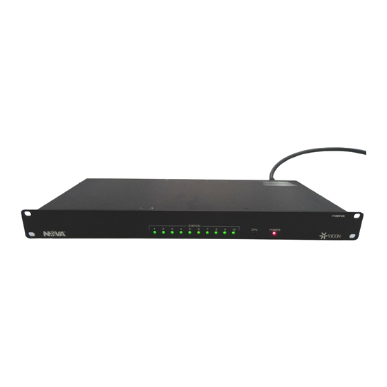
V1400X-IDL Intelligent Distribution Line Control
Vicon Industries Inc. does not warrant that the functions contained in this equipment will meet
your requirements or that the operation will be entirely error free or perform precisely as
described in the documentation. This system has not been designed to be used in life-critical
situations and must not be used for this purpose.
Copyright © 2002 Vicon Industries Inc. All rights reserved.
Product specifications subject to change without notice.
Vicon and its logo are registered trademarks of Vicon Industries Inc.
VICON INDUSTRIES INC., 89 ARKAY DRIVE, HAUPPAUGE, NEW YORK 11788
TEL: 631-952-CCTV (2288) FAX: 631-951-CCTV (2288) TOLL FREE: 800-645-9116
24-Hour Technical Support: 800-34-VICON (800-348-4266)
UK: 44/(0) 1489-566300 INFOFAX: 800-287-1207 WEB: www.vicon-cctv.com
Vicon Part No. 8009-8017-01-00 Section 11 Rev 702
Advertisement
Table of Contents

Related Manuals for Vicon V1400X-IDL


Summary of Contents for Vicon V1400X-IDL
- Page 1 XX017-01-00 V1400X-IDL Intelligent Distribution Line Control Vicon Industries Inc. does not warrant that the functions contained in this equipment will meet your requirements or that the operation will be entirely error free or perform precisely as described in the documentation. This system has not been designed to be used in life-critical situations and must not be used for this purpose.
-
Page 5: Table Of Contents
Requirements and Characteristics ......................13 Addressing ..............................13 Basics................................. 13 Operation Verification Procedure ......................15 Input Devices.............................. 15 Output Devices............................15 CPU Control System Operation........................15 MAINTENANCE ......................... 16 Contents • • • • 1 XX017-01-00 Rev 702 V1400X-IDL Intelligent Distribution Line Control... - Page 6 CPUs ................................18 Input Devices.............................. 18 Output Devices............................18 TECHNICAL INFORMATION..................... 19 ELECTRICAL............................19 CONTROLS & CONNECTORS......................19 OPERATIONAL ............................20 MECHANICAL ............................20 ENVIRONMENTAL..........................20 2 • • • • Contents XX017-01-00 Rev 702 V1400X-IDL Intelligent Distribution Line Control...
-
Page 7: Quick Installation
Quick Installation Quick Installation • • • • 3 XX017-01-00 Rev 702 V1400X-IDL Intelligent Distribution Line Control... -
Page 8: Introduction
This manual covers the installation and operation of the Vicon V1400X-IDL Intelligent Distribution Line Control (IDL). The V1400X-IDL will be referred to as the IDL throughout this manual. The installation procedures should only be performed by a qualified technician using approved materials in accordance with national, state and local wiring codes. -
Page 9: How To Use This Manual
This manual was designed to provide the best overall instructions for the installation and operation of the V1400X-IDL Intelligent Distribution Line Control. The graphics and terminology used in this manual have been carefully selected to enable a clear and distinct understanding of the IDL and its components. This manual has been formatted to present distinct methods of installation for experienced and novice installers. -
Page 10: Installation
Open the cartons and inspect the equipment for damage. Save the cartons and packing material. If damage is present, contact the carrier and file a damage claim immediately. If the equipment must be returned to Vicon for repair, follow the instructions in the Shipping Information Section of this manual. -
Page 11: Cpu Connection
Figure 5 for connection. NOTE: STAT 1/J1 is used to represent any of the 6- position Panel Connectors. Figure 4 J1-J10 Pin Definition for I/O Device Cable Installation • • • • 7 XX017-01-00 Rev 702 V1400X-IDL Intelligent Distribution Line Control... - Page 12 In - signal (Pin 5) and Ground (Pin 4) when using the port. Figure 5 STAT 1 (J1) - STAT 10 (J10) Pin Definition for V1300X-DVC/RVC Cable 8 • • • • Installation XX017-01-00 Rev 702 V1400X-IDL Intelligent Distribution Line Control...
-
Page 13: V1400X-Dvc System Console
System Console units to the V1400X-DVC Master System Console. Figure 6 STAT 1 (J1) - STAT 10 (J10) Pin Definition for V1400X-DVC Cable Installation • • • • 9 XX017-01-00 Rev 702 V1400X-IDL Intelligent Distribution Line Control... -
Page 14: Receivers And Domes
Response In - signal (Pin 5) and Ground (Pin 4) when using the port. Figure 8 STAT 1 (J1) - STAT 10 (J10) Pin Definition for V1319R Cable 10 • • • • Installation XX017-01-00 Rev 702 V1400X-IDL Intelligent Distribution Line Control... -
Page 15: Connector Applications (Surveyor2000)
Figure 10 STAT 1 (J1) - STAT 10 (J10) Pin Definition for STAT 1 (J1) - STAT 10 (J10) Pin Definition for V7UVS Cable V1311RB Cable Installation • • • • 11 XX017-01-00 Rev 702 V1400X-IDL Intelligent Distribution Line Control... - Page 16 STAT 1 (J1) - STAT 10 (J10) Pin Definition for Surveyor2000 Cable NOTE: The RJ-45 connector can be used instead of the Terminal Block on the Surveyor2000. 12 • • • • Installation XX017-01-00 Rev 702 V1400X-IDL Intelligent Distribution Line Control...
-
Page 17: Operation
Operation The V1400X-IDL allows up to 10 I/O Devices to be connected to CPU-based Matrix systems. Since the V1400X-IDL has panel indicators and no controls, individual I/O Devices are used for operation. Refer to the Reference Section of this manual for I/O Device and CPU Instruction Manual numbers. - Page 18 NOTE: Do not connect Input Devices (Keypads/System Consoles) and Output Devices (Receivers/Domes) to the same IDL unit, as they will not operate correctly. Figure 16 Typical System Setup With Daisy-Chained IDLs 14 • • • • Operation XX017-01-00 Rev 702 V1400X-IDL Intelligent Distribution Line Control...
-
Page 19: Operation Verification Procedure
To properly control Cameras and Monitors on various CPU systems, it is necessary to setup monitor partitioning and camera seize control on the CPU. Refer to the appropriate CPU Instruction Manual for information on establishing monitor partitioning and camera seize control. Operation • • • • 15 XX017-01-00 Rev 702 V1400X-IDL Intelligent Distribution Line Control... -
Page 20: Maintenance
Maintenance This unit does not require any scheduled maintenance. If a unit does not operate and replacement of the fuse, as described below, does not correct the problem, contact Vicon’s Service Department. Fuse Replacement If the unit is plugged into a known good outlet, and does not display an illuminated Power LED, replace the Fuse. -
Page 21: Shipping Instructions
Shipping Instructions Use the following procedure when returning a unit to the factory: 1. Call or write Vicon for a Return Authorization (R.A.) at one of the locations listed below. Record the name of the Vicon employee who issued the R.A. -
Page 22: Reference
Universal Receiver X871 V1319R Dual Station Receiver X825 V15UVS Omniscan Dome X806 V7UVS Surveyor Mini Dome X971 V5UVS Surveyor 99 Dome X978 SUR2000 Surveyor2000 Mini-Dome XX031 18 • • • • Reference XX017-01-00 Rev 702 V1400X-IDL Intelligent Distribution Line Control... -
Page 23: Technical Information
Slide switch on rear panel used to toggle the intelligent mode on and off (DL = non-intelligent mode/ IDL intelligent mode). Unit must be reset (temporarily unplugged) for the mode change to take effect. Technical Information • • • • 19 XX017-01-00 Rev 702 V1400X-IDL Intelligent Distribution Line Control... -
Page 24: Operational
Storage Temperature Range: -40° to 150° F (-40° to 65° C). Storage Humidity Range: Up to 90% relative, noncondensing. Figure 18 Front and Rear Panel Views 20 • • • • Technical Information XX017-01-00 Rev 702 V1400X-IDL Intelligent Distribution Line Control... - Page 25 Vicon Industries Inc. Corporate Headquarters 89 Arkay Drive Hauppauge, New York 11788 631-952-CCTV (2288) 800-645-9116 Fax: 631-951-CCTV (2288) !Infofax: 800-287-1207 Vicon Europe Headquarters Brunel Way Fareham, PO15 5TX United Kingdom +44 (0) 1489 566300 Fax: +44 (0) 1489 566322 Brussels Office...
Need help?
Do you have a question about the V1400X-IDL and is the answer not in the manual?
Questions and answers