Table of Contents
Advertisement
Quick Links
ZP755WV-2R Addressable Weatherproof
Sounder/Visual Indicator Installation Sheet
Description
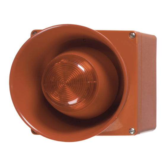
The ZP755WV-2R is an addressable, weatherproof
sounder/visual indicator, designed for use on Ziton analogue
addressable fire detection and alarm systems. The sounder is
rated for outdoor, wet applications. It provides both audible and
visible warnings from a single, addressable, loop-wired unit.
Note:
The visual indicator of this product does not comply with
EN 54-23 and must not be used in fire alarm installations
where fire notification beacons are required.
The sounder includes a volume control, an address-setting
switch, programmable tone settings, and a pair of jumpers to
select the operating power — from the analogue addressable
loop or an external supply.
Installation
To install the device;
1.
Wire the PCB
2.
Set the operating power
3.
Set the address
4.
Set the operating mode
5.
Set the tone
6.
Set the volume
7.
Mount the sounder to the backbox
The details of each step are given below.
Wiring the PCB
Connect the loop wiring and the optional external power cables
to the terminals on the PCB as shown in Figure 1.
© 2014 UTC Fire & Security. All rights reserved.
Figure 1: Connecting the wiring
5
1.
PCB
3067-01
2.
Six-way terminal connector
3.
Header socket
Setting the operating power
The sounder includes a pair of power selection jumpers, J1
and J2. To select from where the sounder obtains its operating
power, position the jumpers as shown in Figure 2.
Figure 2: Power selection jumper configuration
1.
Loop powered
Note:
When using an external power supply, use only one that
is CE and EN 54-4 compliant to power all the sounders on the
same loop.
Setting the address
The sounder includes a seven-segment DIP switch (SW1) for
assigning device addresses. Each switch segment has a
decimal value as shown in Figure 3. The address is the sum of
all the switch segments in the ON position. The switch may be
set to represent any address from 1 to 127.
For example, to select a device address of 007, set SW1-1,
SW1-2, and SW1-3 to the ON position and the remaining
switch segments to the OFF position.
1 / 4
1
24 V O L T S
0 V O L T S
S C R E E N
3
1
4.
5.
1
J1
J2
P/N 501-1787ZE-1-09 • REV 09 • ISS 16APR14
2
( _ V E LO O P )
(+V E LO O P )
4
Connect to sounder
External power
2
J1
J2
2.
External 24 VDC
Advertisement
Table of Contents

Subscribe to Our Youtube Channel
Related Manuals for Ziton ZP755WV-2R


Summary of Contents for Ziton ZP755WV-2R
- Page 1 The ZP755WV-2R is an addressable, weatherproof The sounder includes a pair of power selection jumpers, J1 sounder/visual indicator, designed for use on Ziton analogue and J2. To select from where the sounder obtains its operating addressable fire detection and alarm systems. The sounder is power, position the jumpers as shown in Figure 2.
- Page 2 Setting the tone Two different tones can be programmed to operate from the panel. In ZP755WV-2R mode these tones are selected using SW2-1, SW2-2, and SW2-3. Refer to Table 2. Note: In the ZP panel I/O mapping menu, outputs are programmed as "steady"...
- Page 3 Sounders per loop The ZP755WV-2R sounder can be powered directly from the loop of a ZP3 panel. Use Table 3, in conjunction with Figure 7, to determine the quantity of detectors and sounders that can be connected to a two-core shielded loop.
- Page 4 Sound output level Self test facility disposed of as unsorted municipal waste in Compatibility Ziton addressable systems the European Union. For proper recycling, return this product to your local supplier Addressing method 7-segment DIP switch...
Need help?
Do you have a question about the ZP755WV-2R and is the answer not in the manual?
Questions and answers