Table of Contents

Summary of Contents for Avalue Technology HID-2432
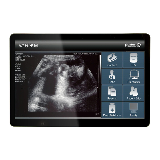
- Page 1 Avalue Intelligent Display & System HID-2432 24" Multi-Touch Medical Panel PC User Manual Ed- 13 August 2020 Copyright © 2020 Avalue Technology Inc., All Rights Reserved. DMR No: T45250-00 Part No: E2017H420A1R Rev: 2...
- Page 2 Purposes and Applications HID-2432 is intended to be used in healthcare institutions for general purpose as an assisting device for data access – patient information, medical records, media services, and so on. The product is designed for general or special use in the hospital environment.
- Page 3 The equipment has been exposed to moisture. The equipment does not work well, or you cannot get it to work according to the user's manual. The equipment has been dropped and damaged. The equipment has obvious signs of breakage. HID-2432 Quick Reference Guide...
- Page 4 Caution! Do not replace battery yourself. Please contact . The computer is provided with a battery-powered real-time clock circuit. There is a danger of explosion if battery is incorrectly replaced. Replace only with same or equivalent type recommended by the manufacture. Discard HID-2432 Quick Reference Guide...
- Page 5 IEC 60065 for video equipment, IEC 61010-1 for laboratory equipment, and IEC 60601-1 for medical equipment.) Furthermore, all configurations shall comply with the system standard IEC 60601-1-1. Everybody who connects additional equipment to the signal input part or signal output part configures HID-2432 Quick Reference Guide...
- Page 6 Warning! Do not modify this equipment without authorization of the manufacturer. Warning! To avoid risk of electric shock, this equipment must only be connected to a supply main with protective earth. Caution! This adapter Delta MDS-090AAS24F is a forming part of the medical device. HID-2432 Quick Reference Guide...
- Page 7 HID-2432 User Manual Explanation of Graphical Symbols Warning: dangerous voltage Caution Note ISO 7000-1641: Follow operating instructions or Consult instructions for use. Direct current. Equipotential Stand-by US Conformance Follow the national requirements for disposal of equipment. HID-2432 Quick Reference Guide...
- Page 8 Reorient or relocate the receiving antenna. Increase the separation between the equipment and receiver. Connect the equipment into an outlet on a circuit different from the one the receiver is HID-2432 Quick Reference Guide...
- Page 9 Selection of other channels is not possible. The antenna(s) used for this transmitter must not be co-located or operating in conjunction with any other antenna or transmitter. Shielded interface cables must be used in order to comply with emission limits. HID-2432 Quick Reference Guide...
- Page 10 EMI sensitive devices in its surrounding which may malfunction therefore. Environmental protection Follow national requirements to dispose of unit. Manufacturer Avalue Technology Inc. 7F, No.79, Lide St., Zhonghe District, New Taipei City, 235, Taiwan TEL: +886-2-8226-2345 FAX: +886-2-8226-2777 Web: www.avalue.com.tw Information: sales@avalue.com.tw HID-2432 Quick Reference Guide...
-
Page 11: Table Of Contents
HID-2432 User Manual CONTENT 1. HID-2432 Multi Touch Medical Panel PC Features ........ 13 1.1 Packing List ..................13 1.2 Specifications ..................14 1.3 Front view ..................17 1.4 Rear & Bottom view ................18 1.5 System Dimensions ................19 2. - Page 12 4.4.23 Front Panel2 touch button connector (JFP2) ......45 4.4.24 DICOM Power connector (JDICOM_PWR2) ......46 4.5 HID-2432 DB Jumper and Connector list .......... 47 4.6 HID-2432 DB Jumpers & Connectors settings ........48 4.6.1 USB connector 1/2 (JUSBU-1/2) ..........48 4.6.2 USB connector 1/2 (JUSBD-1/2) ..........
-
Page 13: Hid-2432 Multi Touch Medical Panel Pc Features
HID-2432 User Manual 1. HID-2432 Multi Touch Medical Panel PC Features ▬▬▬▬▬▬▬▬▬▬▬▬▬▬▬▬▬▬▬▬▬▬▬▬▬▬▬▬▬▬▬▬▬▬ In this chapter, you will get to know all features of our HID-2432 Multi Touch Medical Panel PC. 1.1 Packing List 1 x HID-2432 Medical Panel PC ... -
Page 14: Specifications
HID-2432 User Manual 1.2 Specifications System Mother Board Modified ARC-SKLU for HID-2432 6th Gen Intel® Core™ i5-6300U, 2-Core, 2.4GHz processor (15W) CPU Cooler (Type) Heatsink Memory One 204-pin SODIMM Socket Up to 16GB DDR4 2133 SDRAM Power Supply DC in... - Page 15 Vibration Test 4 Test time : 30 minutes each axis 5 System condition : operation mode 6 Test curve Sine Vibration Test Reference IEC60068-2-6 Testing procedures Test Fc : Vibration sinusoidal 1 Test Acceleration : 2G HID-2432 Quick Reference Guide...
- Page 16 0 ~ 90% Relative Humidity, Non-condensing Storage and -20 ~ 60 degree, 10%~90%@35°C, non-condensing Transportation Condition Atmospheric Pressure 50 ~ 106kPa Expected Service Life 23989hrs Other Test DIN 6868157 Note: Specifications are subject to change without notice. HID-2432 Quick Reference Guide...
-
Page 17: Front View
HID-2432 User Manual 1.3 Front view Power on/off DICOM Mode Touch Volume Reading Light Brightness On/Off Up/down On/Off Up/down HID-2432 Quick Reference Guide... -
Page 18: Rear & Bottom View
LAN: for internet connection COM: for Mouse/Ethernet..etc serial port device HDMI: for display output Note! Equipotential terminal needs to be linked to the hospital ground/earth system before booting the system to protect both operator and system HID-2432 Quick Reference Guide... -
Page 19: System Dimensions
HID-2432 User Manual 1.5 System Dimensions (Unit: mm) HID-2432 Quick Reference Guide... -
Page 20: Setting Up Hid-2432 Multi Touch Panel Pcs
HID-2432 User Manual 2. Setting Up HID-2432 Multi Touch Panel PCs ▬▬▬▬▬▬▬▬▬▬▬▬▬▬▬▬▬▬▬▬▬▬▬▬▬▬▬▬▬▬▬▬▬▬ This chapter gives instructions on how to set up HID-2432 Multi Touch Panel PC and how to connect different cables. 2.1 VESA Mounting 2.2 Cleaning and Disinfecting HID-2432 Quick Reference Guide... -
Page 21: Vesa Mounting
Installation instructions follow: First attach the wall-mounting to the heat-sink of the HID-2432, securing it in place with four of the M4 x 6mm screws provided. Mount the on the wall, stand or other flat surface. - Page 22 HID-2432 User Manual Suggested Screw type for mounting Note: 4 pieces of M4 x 6mm screws (P/N: E1933050611R) Warning! Use suitable mounting apparatus to avoid risk of injury. HID-2432 Quick Reference Guide...
-
Page 23: Cabling
Follow below step Connecting the Ground pin 1. With system ready, find the equipotential terminal on the rear side of the HID-2432. An equipotential terminal is provided to optionally connect to a hospital ground/earth system. 2. Prepare grounding cable and the other terminal links to the hospital ground/ earth system. - Page 24 HID-2432 User Manual Please follow below steps to connect power cable to system. The HID-2432 could only be powered by a DC power adapter (Delta MDS-090AAS24F). Be sure to always handle the power cords by holding the plug ends only.
-
Page 25: Cleaning And Disinfecting
HID-2432 User Manual 2.3 Cleaning and Disinfecting During normal use of HID-2432, the device may become dirty and should be regularly cleaned. Cleaning Instructions 1. Turn off the computer before starting clean up. This way, you can see any dirt on the screen; the brightness of the monitor may make you miss some areas. -
Page 26: Using Hid-2432 Multi Touch Panel Pcs
HID-2432 User Manual 3. Using HID-2432 Multi Touch Panel PCs ▬▬▬▬▬▬▬▬▬▬▬▬▬▬▬▬▬▬▬▬▬▬▬▬▬▬▬▬▬▬▬▬▬▬ This chapter describes in detail all features of HID-2432 Multi Touch Panel PC. 3.1 Turn ON/OFF the System 3.2 Using LCD Display and Touch Screen HID-2432 Quick Reference Guide... -
Page 27: Turn On/Off The System
1. Press on the Power ON/OFF icon firmly for 4 seconds. 2. The Power ON/OFF LED will turns orange to indicate power is off. 3. Your system is turned OFF. Note: We recommend using operating system shut down procedure to turn the system OFF. HID-2432 Quick Reference Guide... -
Page 28: Using Lcd Display And Touch Screen
3. Press LED reading light icon for 4 secs to turn off the touch function (touch function always on as default) 4. Press LED reading light icon for 4 secs to turn on the touch function HID-2432 Quick Reference Guide... -
Page 29: Dicom Settings
And please note that brightness cannot be adjusted under DICOM mode. The brightness up/ down buttons are only functional under normal mode. Power on/off DICOM Mode HID-2432 Quick Reference Guide... -
Page 30: Hardware Configuration
HID-2432 User Manual 4. Hardware Configuration 4.1 HID-2432 MB Overviews HID-2432 Quick Reference Guide... -
Page 31: Hid-2432 Db Overviews
HID-2432 User Manual 4.2 HID-2432 DB Overviews HID-2432 Quick Reference Guide... -
Page 32: Hid-2432 Mb Jumper And Connector List
HID-2432 User Manual 4.3 HID-2432 MB Jumper and Connector list Jumpers Label Function Note Clear CMOS 3 x 1 header, pitch 2.00mm JCOMS1 Serial port 1/2 pin9 signal select 3 x 2 header, pitch 2.00mm JRI1/2 Serial port 1 in RS-232/422/485 4 x 3 header, pitch 2.00mm... - Page 33 SPI connector EC Debug connector JEC1 2 x 1 header, pitch 2.00 mm SATA1 Serial ATA connector 2 x 1 wafer, pitch 2.00mm SATAPW1 SATA Power connector JDICOM_PWR2 DICOM Power connector 6 x 1 wafer, pitch 2.00mm HID-2432 Quick Reference Guide...
-
Page 34: Hid-2432 Mb Jumpers & Connectors Settings
HID-2432 User Manual 4.4 HID-2432 MB Jumpers & Connectors settings 4.4.1 Clear CMOS (JCOMS1) Protect* Clear CMOS *Default 4.4.2 Serial port 1/2 pin9 signal select (JRI1/JRI2) Ring* +12V JRI1 JRI2 * Default HID-2432 Quick Reference Guide... -
Page 35: Display Port Power Selector (Jpg3)
HID-2432 User Manual 4.4.3 Display Port power selector (JPG3) +3.3V* +12V * Default 4.4.4 AT/ATX auto power on select (JAT1) ATX* * Default HID-2432 Quick Reference Guide... -
Page 36: Serial Port 1 In Rs-232/422/485 Mode (Jcom1_Sel1)
COM1-3 422RX1+ NRXDA COM1-2 485_422TX1+ NDTRA# 11 COM1-4 12 422RX1- Note: This connector is available after modify the mode of COM1 in BIOS setting. * Default 4.4.6 On-board header for USB2.0 (JUSB1) Signal +5VSB USB_z_PN10 USB_z_PP10 HID-2432 Quick Reference Guide... -
Page 37: On-Board Header For Usb2.0 (Jusb2)
HID-2432 User Manual 4.4.7 On-board header for USB2.0 (JUSB2) Signal PIN PIN Signal +5VSB +5VSB USB_z_PN6 USB_z_PN5 USB_z_PP6 USB_z_PP5 4.4.8 On-board header for USB2.0 (JUSB3) Signal +5VSB USB_WF_PN9 USB_WF_PP9 HID-2432 Quick Reference Guide... -
Page 38: Battery Connector (Jbat1)
HID-2432 User Manual 4.4.9 Battery connector (JBAT1) Signal +RTCBAT 4.4.10 Display Port connector (JDP1) Signal PIN PIN Signal +V312_DP +V312_DP DP_TXP2 DP_HPD1 DP_TXN2 AUXP_IN DP_TXP1 AUXN_IN DP_TXN1 DP_TXP0 DP_TXP3 DP_TXN0 DP_TXN3 HID-2432 Quick Reference Guide... -
Page 39: Speaker_R (Jspr1)
HID-2432 User Manual 4.4.11 Speaker_R (JSPR1) Signal SPK_R- SPK_R+ 4.4.12 Speaker_L (JSPL1) Signal SPK_L- SPK_L+ HID-2432 Quick Reference Guide... -
Page 40: Spi Connector (Jspi1)
HID-2432 User Manual 4.4.13 SPI connector (JSPI1) Signal PIN PIN Signal +3.3VSB SPI0_CS0# SPI_CLK SPI_SO SPI_SI HOLD# 4.4.14 EC Debug connector (JEC1) Signal EC_SMCLK_DEBUG EC_SMDAT_DEBUG HID-2432 Quick Reference Guide... -
Page 41: Ups-Gpio Connector (Jups1)
HID-2432 User Manual 4.4.15 UPS-GPIO connector (JUPS1) Signal PIN PIN Signal DC_JACK_OFF# SMB_CLK SMB_DATA 4.4.16 LED connector (JLED1) Signal +5VSB LED_BOARD_EN HID-2432 Quick Reference Guide... -
Page 42: B2B Connector (Jb2B1)
PCIE_RXN8 PCIE_RXP8 HDMI1_CLKN Signal PIN PIN Signal HDMI1_CLKP CLK_B2BPCIE_N2 CLK_B2BPCIE_P2 +12V MIC_RIN +12V MIC_LIN MIC1_JD LPC_SERIRQ 46 +5VSB LINEOUT1_JD LINE1_JD LPC_LFRAME# 47 +5VSB LINEOUT_R LINE1_RIN CLK3_LPC_B2B 48 +5VSB LINEOUT_L LNE1_LIN LPC_AD0 49 +5VSB LPC_AD1 50 +5VSB HID-2432 Quick Reference Guide... -
Page 43: Sata Power Connector (Satapw1)
HID-2432 User Manual 4.4.18 SATA Power connector (SATAPW1) Signal 4.4.19 Power connector (JPWR4) Signal +VIN_12-26V +VIN_12-26V HID-2432 Quick Reference Guide... -
Page 44: General Purpose I/O Connector (Jgpio1)
HID-2432 User Manual 4.4.20 General purpose I/O connector (JGPIO1) Signal PIN PIN Signal +3.3V SMB_DATA SMB_CLK DIO_GP23 DIO_GP13 DIO_GP22 DIO_GP12 DIO_GP21 DIO_GP11 DIO_GP20 DIO_GP10 4.4.21 EC General purpose I/O connector (JGPIO2) Signal DICOM_GPIO-1 DICOM_GPIO-2 DICOM_GPIO-3 DICOM_GPIO-4 HID-2432 Quick Reference Guide... -
Page 45: Front Panel1 Connector (Jfp1)
HID-2432 User Manual 4.4.22 Front Panel1 connector (JFP1) Signal PWBT RST# PWR-LED- PWR-LED+ HDD-LED- HDD-LED+ LAN1-Active LAN2-Active 4.4.23 Front Panel2 touch button connector (JFP2) Signal PIN PIN Signal FP_LED1 FP_LED2 TOUCH_PWRBTN# LED_BOARD_ONOFF# BRI_DN# BRI_UP# VOL_DN# VOL_UP# +3VLP HID-2432 Quick Reference Guide... -
Page 46: Dicom Power Connector (Jdicom_Pwr2)
HID-2432 User Manual 4.4.24 DICOM Power connector (JDICOM_PWR2) Signal +12V +12V +24V +24V HID-2432 Quick Reference Guide... -
Page 47: Hid-2432 Db Jumper And Connector List
HID-2432 User Manual 4.5 HID-2432 DB Jumper and Connector list Jumpers Label Function Note USB connector 1/2 3 x 1 header, pitch 2.00mm JUSBU-1/2 USB connector 1/2 3 x 1 header, pitch 2.00mm JUSBD-1/2 JUSBS4 USB power selector 3 x 1 header, pitch 2.00mm JCOM1/2SEL1 COM1/2 in RS-232/422/485 mode 3 x 2 header, pitch 2.00mm... -
Page 48: Hid-2432 Db Jumpers & Connectors Settings
HID-2432 User Manual 4.6 HID-2432 DB Jumpers & Connectors settings 4.6.1 USB connector 1/2 (JUSBU-1/2) USB Full Speed* USB Low Speed JUSBU-2 JUSBU-1 Note: Low speed: compatible with Keyboard/ mouse. *Default Full speed: compatible with USB drive, Keyboard/ Mouse receiver. -
Page 49: Usb Power Selector (Jusbs4)
HID-2432 User Manual 4.6.3 USB power selector (JUSBS4) Charged after shutdown* Uncharged after shutdown *Default 4.6.4 COM1/2 in RS-232/422/485 mode (JCOM1/2SEL1) RS232* RS485 JCOM2SEL1 JCOM2SEL1 RS422 *Default HID-2432 Quick Reference Guide... -
Page 50: Serial Port 1 Connector (Jcom1)
HID-2432 User Manual 4.6.5 Serial port 1 connector (JCOM1) Signal PIN PIN Signal NTXD1 NRXD1 NDCD1# NDTR1# 4.6.6 Serial port 2 connector (JCOM2) Signal PIN PIN Signal NTXD2 NRXD2 NDCD2# NDTR2# HID-2432 Quick Reference Guide... -
Page 51: B2B Connector (B2B1)
LAN_CLKREQ# HDMI1_TXN1 HDMI1_TXP1 PCIE_TXN PCIE_TXP HDMI1_TXN0 HDMI1_TXP0 PCIE_RXN Signal PIN PIN Signal PCIE_RXP HDMI1_CLK_N HDMI1_CLK_P PCIE_CLKN PCIE_CLKP MIC_R LPC_SERIRQ +5VSB MIC_L MIC_JD LPC_FRAME# +5VSB LPC_CLK +5VSB LINEOUT_JD LINEIN_JD LPC_AD0 +5VSB LINE_R_OUT LINE_R_IN LPC_AD1 +5VSB LINE_L_OUT LINE_L_IN HID-2432 Quick Reference Guide... -
Page 52: Usb Connector 4 (Jusb4)
Signal LINE_L_OUT LINE_R_OUT LINE_L_IN LINE_R_IN MIC_L MIC_R LINEIN_JD LINEOUT_JD MIC_JD 4.6.9.1 Signal Description – Audio connector (JMIC1) Signal Signal Description LINEOUT_JD AUDIO Out(ROUT/LOUT) sense pin MIC_JD MIC IN (MIC_RIN/LIN) sense pin Note: Line in function unavailable. HID-2432 Quick Reference Guide... -
Page 53: General Safety Guide
You want to remove/install any parts Thermal The HID-2432 is a fanless design system, heat is dispatch through rear metal heatsink which is located at VESA mount area.. When using your HID-2432 systems, it is normal for the metal heatsink to get warm. The rear metal heatsink of the HID-2432 functions as a cooling surface that transfers heat from inside the computer to the cooler air outside. - Page 54 Handle your HID-2432 with care. It is made of metal, glass, and plastic and has sensitive electronic components inside. Don't use a damaged HID-2432, such as one with a cracked screen, as it may cause injury. Setup HID-2432 on a stable work surface.
Need help?
Do you have a question about the HID-2432 and is the answer not in the manual?
Questions and answers