
Related Manuals for Nokia Flexi Zone Pico


Summary of Contents for Nokia Flexi Zone Pico
- Page 1 Nokia Networks LTE Radio Access, Rel. RL70, Operating Documentation, Issue 02, Documentation Change Delivery 2 Flexi Zone Indoor Pico BTS Product Description DN09210454 Issue 01 Approval Date 2015-04-28 ...
- Page 2 (“Agreement”) under which this document is distributed. No part of this document may be used, copied, reproduced, modified or transmitted in any form or means without the prior written permission of Nokia Solutions and Networks. If you have not entered into an Agreement applicable to the Product, or if that Agreement has expired or has been terminated, You may not use this document in any manner and You...
-
Page 3: Table Of Contents
Flexi Zone Indoor Pico BTS Product Description Table of Contents This document has 34 pages Summary of changes..............6 Introduction to Flexi Zone Indoor Pico BTS........7 Benefits..................8 Flexi Zone Indoor Pico BTS Specifications........9 Construction................. 10 Interfaces..................10 Reset button.................12 PoE-++ solution................12 Installation options............... 14 Air Interface..................17 Air interface configuration............17 Supported bandwidth..............17 Diversity..................19 RF Output Power................. - Page 4 Flexi Zone Indoor Pico BTS Product Description List of Figures Figure 1 Flexi Zone Indoor Pico BTS..............7 Figure 2 Contents of delivery................10 Figure 3 Flexi Zone Indoor Pico module interfaces (with external antenna connectors)..................11 Figure 4 Flexi Zone Indoor Pico module interfaces (without external antenna connectors)..................11 Figure 5 One-port injector.................13 Figure 6 Multi-port injector................13 Figure 7 Mounting Flexi Zone Indoor Pico onto a wall........15 Figure 8 Mounting Flexi Zone Indoor Pico onto a pole........15 Figure 9 Mounting Flexi Zone Indoor Pico onto a ceiling........16 Figure 10 Maximum GPS Receiver Interference Power Level vs. Frequency..23 Figure 11 LED indicators..................25 Figure 12 Recommended ceiling location............32 Figure 13 Recommended wall location...............33 Figure 14 Recommended corridor location............33 DN09210454 Issue: 01...
- Page 5 Flexi Zone Indoor Pico BTS Product Description List of Tables Table 1 Releases covered by the document............. 6 Table 2 Flexi Zone Indoor Pico BTS Specifications.......... 9 Table 3 Interfaces description................11 Table 4 PoE-++ specification................12 Table 5 Nokia recommended midspan devices..........14 Table 6 Flexi Zone Pico Indoor BTS supported LTE bandwidth variants..17 Table 7 Flexi Zone Pico Indoor BTS supported WCDMA bandwidth variants..Table 8 Flexi Zone Pico Indoor external antenna requirements / recommendations................19 Table 9 Recommended GPS / GLONASS Antenna Specifications....21 Table 10 GPS sensitivity requirements............. 22 Table 11 FZM and FZP LED indications............25 Table 12 Flexi Zone Pico WiFi LED states............30 Issue: 01 DN09210454...
-
Page 6: Summary Of Changes
Summary of changes Flexi Zone Indoor Pico BTS Product Description 1 Summary of changes Changes between document issues are cumulative. Therefore, the latest document issue contains all changes made to previous issues. Table 1 Releases covered by the document Product Release Long Term Evolution RL70, FDD-LTE 15A TD LTE RL55TD, TDD-LTE 15A This is the first issue of the document. DN09210454 Issue: 01... -
Page 7: Introduction To Flexi Zone Indoor Pico Bts
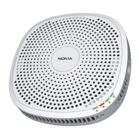
Flexi Zone Indoor Pico BTS Product Description Introduction to Flexi Zone Indoor Pico BTS 2 Introduction to Flexi Zone Indoor Pico BTS The Flexi Zone Indoor Pico BTS is a small cell optimized for an indoor environment. The Flexi Zone Indoor Pico BTS provides seamless mobility and enhanced user experience in enterprise and public indoor locations by cost effectively improving the coverage and capacity of the network, delivering the best subscriber mobile broadband experience. The main application of this BTS is to deliver an improved mobile broadband experience by offloading data traffic from macro networks. Thanks to its small size and a fanless solution, the BTS can be easily and quickly deployed in strategic locations to add coverage and capacity. The Flexi Zone Indoor Pico BTS features a compact single enclosure. The Flexi Zone Pico is a fully compliant 3GPP solution and supports standard network interfaces to other network elements, such as S1 and X2 in LTE and Iub interface towards a controller in WCDMA. It allows the use of the same software as used in macro base stations and can easily integrate into Heterogenous Networks (HetNets). The hardware platform supports full throughput capability of 5 (only FDD), 10, 15, or 20 MHz LTE carriers with 2x2 MIMO (LTE main and diversity transmit). The WCDMA version supports 5 MHz bandwidth with 2Tx2Rx at BTS side and Virtual Antenna Mapping solution. The physical transport interface is optimized for IP-based transport solutions. Furthermore, the BTS supports varying transmit power up to 250 mW per antenna branch. Figure 1 Flexi Zone Indoor Pico BTS Issue: 01 DN09210454... -
Page 8: Benefits
Benefits Flexi Zone Indoor Pico BTS Product Description 3 Benefits Flexi Zone Pico Indoor BTS provides a vast number of benefits for the operator. Ease of deployment Flexi Zone Pico Indoor BTS offers new site deployment possibilities thanks to its compact size and light weight ( < 3 kg ( < 6.61 lb.)), which makes it easy and fast to deploy. It can be used in existing buildings using Ethernet cabling for backhaul that significantly lower the costs in comparison to traditional systems. The Flexi Zone Indoor Pico can be powered via a PoE++ based solution reducing complexity, cost of ownership and lead to faster deployments. Additionally the Flexi Zone Indorr BTS can be powered by a AC/DC power supply (optional item). Flexi Zone Pico Indoor BTS incurs lower installation cost as it can be deployed by a single person while reducing running costs due to its low power consumption yet high capacity delivery Flexibility in installation Flexi Zone Pico Indoor BTS is specially designed to be installed onto walls, horizontal poles, vertical poles or ceilings, which makes in the perfect BTS for indoor coverage. Refer to Installation options for more details on installation scenarios. Macro Capacity and Full Macro Parity Flexi Zone Indoor Pico integrates easily into Heteregenous Networks (HetNets) as the processing power allows the same software as used in macro base stations. Most features available for macro cells are also available for Flexi Zone Indoor Pico cells, including easy software upgrades to LTE-Advanced (LTE models) and support by the same NetAct Operations and Support System (OSS) as well as iSON. Multiradio Access / Multi Technology (RAT) Flexi Zone Indoor Pico BTS supports both LTE/WCDMA and Wi-Fi access (only variants with Wi-Fi antenna). The module is integrated within a single compact small form factor allowing for reduced number of boxes and shared devices. Additionaly, Flexi Zone Indoor... -
Page 9: Flexi Zone Indoor Pico Bts Specifications
Flexi Zone Indoor Pico BTS Product Description Flexi Zone Indoor Pico BTS Specifications 4 Flexi Zone Indoor Pico BTS Specifications This topic describes Flexi Zone Indoor Pico BTS (both WCDMA and LTE) specifications, such as supported technologies, physical parameters or Wi-Fi information. Table 2 Flexi Zone Indoor Pico BTS Specifications Parameter LTE and LTE + Wi-Fi variant 3G and 3G + Wi-Fi variant 3GPP RAT Support One LTE band One WCDMA band (software upgradable to LTE) Bandwidth Supported 5, 10, 15, 20 MHz software HW support up to two selectable consecutive 5 MHz carriers 3GPP RAT and Wi-Fi Antenna Integrated 2x2 MIMO or external antennas Configuration Power Output 50 mW to 250 mW per Tx 50 mW to 250 mW per Tx path... -
Page 10: Construction
Construction Flexi Zone Indoor Pico BTS Product Description 5 Construction Flexi Zone Indoor Pico BTS consists of the following parts: Core base station module • The core module integrates the following items into one single unit: – baseband functionality – clock and control – external interfaces – transmission – Some variants also contain an integrated Wi-Fi antenna that enables Flexi Zone Indoor Pico BTS to function as a wireless Access Point (AP). See Table 6: Flexi Zone Pico Indoor BTS supported LTE bandwidth variants for available models list. Base station contents of delivery • 1. Mounting Bracket 2. Ceiling clip with screws 3. Tamper-resistant screw and a magnetized wrench 4. Quick start guide Figure 2 Contents of delivery ... -
Page 11: Figure 3 Flexi Zone Indoor Pico Module Interfaces (With External Antenna Connectors)
Flexi Zone Indoor Pico BTS Product Description Construction Flexi Zone Indoor Pico module connection panel differs between modules with and without external antenna connectors as shown in Figure 3: Flexi Zone Indoor Pico module interfaces (with external antenna connectors) and Figure 4: Flexi Zone Indoor Pico module interfaces (without external antenna connectors). Figure 3 Flexi Zone Indoor Pico module interfaces (with external antenna connectors) ANT2 BH#2/LMT Antenna Managment port port Antennaport BH#1/PoE Reset Backhaul button port ANT1 DCport Antenna port Figure 4 Flexi Zone Indoor Pico module interfaces (without external antenna connectors) BH#2/LMT Managment Antenna port BH#1/PoE DCport Reset Backhaul button port See Table 3: Interfaces description for information about differences between modules. -
Page 12: Reset Button
Construction Flexi Zone Indoor Pico BTS Product Description Table 3 Interfaces description (Cont.) Interface Connector type Description BH #2/LMT Management port RJ45 Ethernet connection with the core network or Pico Module management 5V DC port 3.5 mm barrel connector DC in power supply GPS antenna port GPS antenna signal receive ANT1 and ANT2 antenna ports SMA External antennas (LTE/WCDMA) signal transmit and receive 5.2 Reset button The reset button is placed on the connection panel of the Flexi Zone Indoor Pico module. There are two functions of the reset button: A momentary push of the button will result in a hard reset of the device (similar to • power up restart) Pressing and holding the button for more than 5 seconds will trigger the in factory • default reset 5.3 PoE-++ solution Flexi Zone Indoor Pico modules support Power-over-Ethernet Evolution (PoE++) technology to supply the unit with power. The PoE solution allows electrical power to pass along with data on Ethernet cabling. It offers several benefits to the user, including: Cost savings - PoE-++ significantly reduces the number of electrical wiring and... -
Page 13: Figure 5 One-Port Injector
Flexi Zone Indoor Pico BTS Product Description Construction Table 4 PoE-++ specification (Cont.) Parameter Value(s) 42,5 - 57 VDC Voltage range at PD Maximum current 1200 mA total, 300 mA/pair Maximum cable resistance 25 Ohms per loop CAT cable types Cat 5e/6 Maximum cable length 100 m Quantity of conductors used 4 pairs / 8 wires * - PSE refers to a PoE-enabled network switch or a midspan power injector and PD means FZ Indoor Pico Module Power injectors can either be individual or multi-port, as shown in Figure 5: One-port injector and Figure 6: Multi-port injector. Figure 5 One-port injector PowerSupply EthernetCable EthernetCable DataOnly Data+Power Non-PoENetworkSwitch PoEInjector PoEDevice (WirelessAP,CPE,Router,etc...) Individual1portInjector Figure 6 Multi-port injector EthernetSwitch PowerOverEthernet MidspanHub VoIP WirelessLAN... -
Page 14: Installation Options
Construction Flexi Zone Indoor Pico BTS Product Description Nokia products require power injectors that support a 12.5K Ohm detection resistor and provide a power output of 60W per port in a 4PPoE implementation. Nokia recommended midspan devices are listed in the table. Table 5 Nokia recommended midspan devices Manufacturer Model Number of ports Micro-semi PD-9606G Micro-semi PD-9612G Micro-semi PD-9501GR Phihong POE480U-4UP Phihong POE480U-8UP For more information and specifications, check the manufacturers' websites. 5.4 Installation options This chapter describes Flexi Zone Indoor Pico BTS possible installation scenarios, which are wall, pole and ceiling installations. NOTICE: Flexi Zone Indoor Pico BTS equipment must be installed by trained and qualified service personnel in accordance with all local codes and requirements. NOTICE: Flexi Zone Indoor Pico BTS equipment is intended for installation in restricted access location or equivalent. NOTICE: The unit may become hot and should be installed away from any potential sources of moisture (away from heating or cooling ducts, doors/window). Ensure good airflow for the unit to allow proper heat dissipation. NOTICE: The unit should be located away from any RF radiation sources, out of direct sun exposure, and away from a potential salt spray. NOTICE: Avoid installing the device near windows to avoid external interference. -
Page 15: Figure 7 Mounting Flexi Zone Indoor Pico Onto A Wall
Flexi Zone Indoor Pico BTS Product Description Construction Figure 7 Mounting Flexi Zone Indoor Pico onto a wall Flexi Zone Indoor Pico pole installation Flexi Zone Indoor Pico can be mounted onto a vertical or horizontal indoor pole. Use the mounting bracket delivered in the box and band straps to install the Flexi Zone Indoor Pico BTS onto a pole. The band straps are not included within the package and need to be ordered separately. Figure 8 Mounting Flexi Zone Indoor Pico onto a pole Issue: 01 DN09210454... -
Page 16: Figure 9 Mounting Flexi Zone Indoor Pico Onto A Ceiling
Construction Flexi Zone Indoor Pico BTS Product Description Flexi Zone Indoor Pico ceiling installation NOTICE:Ensure that the ceiling grid location is well supported. Use the mounting bracket and the ceiling clip delivered in the box to mount the Flexi Zone Indoor Pico BTS onto a ceiling. Figure 9 Mounting Flexi Zone Indoor Pico onto a ceiling DN09210454 Issue: 01... -
Page 17: Air Interface
Flexi Zone Indoor Pico BTS Product Description Air Interface 6 Air Interface 6.1 Air interface configuration The BTS transceiver supports single band 2 Tx and 2 Rx antenna connections with each transmit port supporting a maximum transmission power of 250 mW per antenna branch and operates within a maximum bandwidth window of 20MHz. 6.2 Supported bandwidth The LTE supported bandwidth is shown in Table 6: Flexi Zone Pico Indoor BTS supported LTE bandwidth variants. Table 6 Flexi Zone Pico Indoor BTS supported LTE bandwidth variants Duplex Operating Uplink (UL) Downlink (DL) Unit's Integrated Antenna Mode name Wi-Fi Band operating band operating band BTS receive BTS transmit UE transmit UE receive... -
Page 18: Table 6 Flexi Zone Pico Indoor Bts Supported Lte Bandwidth Variants
Air Interface Flexi Zone Indoor Pico BTS Product Description Table 6 Flexi Zone Pico Indoor BTS supported LTE bandwidth variants (Cont.) Duplex Operating Uplink (UL) Downlink (DL) Unit's Integrated Antenna Mode name Wi-Fi Band operating band operating band BTS receive BTS transmit UE transmit UE receive – – UL_low DL_low UL_high DL_high FWPC Embedded 703 MHz - 748 758 MHz - 803 FWPD Embedded... -
Page 19: Diversity
Flexi Zone Indoor Pico BTS Product Description Air Interface 6.3 Diversity 2-way receiver diversity is supported. Single receiver configuration is supported by both receivers in case of failure of one of the receivers. Single transmit configuration is supported in case of failure of one of the transmitters or antennas, allowing a transmit mode configuration of Tx Diversity (SIMO). 6.4 RF Output Power Transmit power maximum: 250 mW + 250mW • 24 dBm per branch • Transmit power can be configured in different steps from the maximum down to the transmit power defined for a LTE or WCDMA Local Area class: 250mW + 250mW • 24 dBm (supported commisioning values: from 17 dBm to 24 dBm, step of 1 dB) • 6.5 External RF Antennas Pico indoor variants primarily utilize internal antennas. External antennas are also supported but require additional hardware, as the Pico Indoor radio is not supplied with external antennas or antenna mounting. Guidelines for selecting external antennas Table 8 Flexi Zone Pico Indoor external antenna requirements / recommendations Parameter Requirement / Recommendations Type Application specific (primarily ceiling mount is... - Page 20 Air Interface Flexi Zone Indoor Pico BTS Product Description Maximum Personal Exposure (MPE) / Specific Absorption Rate (SAR) MPE certification testing was performed to determine the Minimum Safe Distance using external antennas with 5dBi gain for 1700 - 2700MHz. The antenna used for this certification was Pulse DASLTE500NFMIMO. Thus, if other external antennas are used, the gain should be equal to or lower than this antenna to maintain the same minimum safe distances specified. If higher gain antennas are used, the Minimum Safe Distance is increased. Please consult your local regulatory requirements. Please reference the actual Pico MPE/SAR reports for further details. Cabling Connection to the Pico SMA-F requires a SMA-M. Adapter cables are required. For best performance direct the antenna main beam away from the Pico. Nokia does not recommend directly attaching rubber-duck stick OMNI antennas directly to the Pico antenna outputs. This is due to the low isolation between the antennas for main and diversity that would result in degrading MIMO performance. To insure optimal performance, high quality low loss cable should be used while keeping the cable length to a minimum. Excessive cable lengths and low quality cable cause significant performance degradation. Lightning and surge protection For indoor use, Flexi Zone Pico does not require surge protection. If the antennas are remotely connected outdoors, then appropriate surge protection is required per the local regulations. Recommended antennas Nokia does not currently supply external antennas, but some examples for recommended antennas are: Galtronics Pear M4969i •...
-
Page 21: Synchronization
Timing over Packet according to IEEE 1588v2 • 7.1 GPS / GLONASS Instead of using the transport network for carrying the Primary Reference Clock (PRC) traceable synchronization reference, it is possible to use a distributed PRC architecture. In this case, every site in the network has a GPS-based or other synchronization source which provides a PRC traceable synchronization reference signal for RAN NEs. It is also possible to use a combination of distributed and hierarchical master-slave architecture. In some cases, other Network Elements (for example transmission nodes) at the same site provide the synchronization reference for RAN Network Elements through external synchronization interfaces. 7.1.1 Overall GPS / GLONASS Antenna RF Requirements Antenna Requirements The Nokia recommended GPS / GLONASS antennas meet all quality and field performance requirements along with criteria outlined in the table below and have proven quality with good field performance. While it is possible to use other antennas, considerable care must be exercised when selecting alternatives to ensure full BTS compatibility for all conditions. Table 9 Recommended GPS / GLONASS Antenna Specifications Requirement / Recommendations Gain +25 dB (recommended) Noise Figure <2.5 dB (recommended) Operating Frequency GPS: 1575.42 MHz with less than 3 dB attenuation at a +1.2 MHz offset from center (Required) -
Page 22: Table 10 Gps Sensitivity Requirements
Tracking -161 dBm Hot Acquisition -161 dBm GPS Sensitivity Cold Acquisition -147 dBm Reacquisition -161 dBm * - Values are valid at room temperature 25 C [77 F] External GPS Antennas Many different GPS antenna options are available for an outdoor GPS antenna. The guidelines in Table 9: Recommended GPS / GLONASS Antenna Specifications also apply to an external GPS/GLONASS receiver. The FlexiZone Micro GPS antenna (473100A) can suit this purpose. This antenna is designed to mount directly to the female N connector on the FZM so does not include a cable or mounting feature. A mounting bracket would be needed with a bulkhead female N connector then a long run of cable. If a deployment of a large number of FZPs is needed with remote GPS then the best solution would be a single GPS antenna and a distribution network. Care must be taken to insure the DC block is in place. This DC block can be a separate item or included in the distribution network. Distribution networks In the case of large indoor deployments of FZP units utilizing GPS/GLONASS it is better to use a single GPS antenna with a distribution network. This equipment is not supplied by Nokia as it is site specific, but can be used to overcome the losses incurred with long cable runs and multiple splits to accommodate separate feeds into each FZP. Care must be taken when selecting the proper distribution amplifier. The key requirements are as follows: Active GPS/GLONASS antenna bias: The amplifier must provide 5 VDC for the • active antenna. Port Impedance: All ports (IN/OUT) must be 50 ohms. • DN09210454 Issue: 01... -
Page 23: Rf Interference
• 32-port Rack mount: RMAL-DCB-S1X32-N/5/110 • These models include the DC Block on all output ports, provide the 5 VDC for the active antenna, utilize N type connections and are powered via 110 VAC. For other AC power options the “110” in the part number above can be replaced with either “220” or “240” depending on the available local power. If utilizing a distribution network insure that all grounding and surge suppression requirements are followed. 7.1.2 RF Interference While the BTS GPS receiver and recommended antennas provide a high level of out of band interference, rejection care needs to be taken to avoid placing the GPS antenna in the direct radiation path of cellular or other transmit antennas. To minimize interference potential the GPS antenna needs to be positioned at a different elevation and as far as possible from nearby transmit antennas. The graph presented in Figure 10: Maximum GPS Receiver Interference Power Level vs. Frequency can be used to identify the maximum interference source power levels presented at the GPS antenna surface (assuming that a Nokia recommended GPS antenna is in use and RF signal presented to the GPS receiver meets all level and noise figure requirements). Different interference rejection performance can be experienced with other (non-Nokia recommended) GPS antenna types or when the GPS receiver is not provided with the required (minimum or maximum) RF signal levels. Figure 10 Maximum GPS Receiver Interference Power Level vs. Frequency Power Level Interferenceabovelimits -5dBm -45dBm -110dBm Interferencewithinlimits Frequency 7.2 Synchronous Ethernet and Synchronous Ethernet generation According to G.8261, Synchronous Ethernet provides a SDH-like mechanism for... -
Page 24: Timing Over Packet
Synchronization Flexi Zone Indoor Pico BTS Product Description SyncE provides a high quality synchronization reference for base stations, comparable to SDH synchronization. The stability of the recovered frequency is independent of the network load or network impairments like delay variations. A co-located or another chained tail site can be synchronized with Synchronous Ethernet generation using SyncE. Both BTS Synchronous Ethernet and Timing over Packet features can be activated simultaneously. The features can be set individually as primary and secondary synchronization sources. When both SyncE and IEEE1588 ToP are feasible in the priority configuration, the selection of ToP or SyncE as primary or secondary references is a key point in the design of the synchronization network and depends very much on the characteristics of the mobile backhaul network being used to access the BTS. In addition, when Synchronous Ethernet Generation feature is activated, both SyncE and Timing over Packet can serve as an input for generating SyncE signal towards chained/collocated BTS. 7.3 Timing over Packet Timing over Packet (ToP) can be also considered as an example of master-slave architecture. The ToP master sends timing packets to ToP slaves. ToP slaves recover the timing reference from the received timing packets. The transport network between the ToP Master and the ToP Slave embedded in the BTS must fulfill certain engineering rules to guarantee proper operation of ToP as synchronization source such that the stability of the frequency for the air interface meets 3GPP requirements (+/-50ppb). These engineering rules are related to the treatment of the IEEE1588 ToP packets in the network and SLA values for Packet Loss and Packet Delay Variation. DN09210454 Issue: 01... -
Page 25: Flexi Zone Pico Led States
Flexi Zone Indoor Pico BTS Product Description Flexi Zone Pico LED states 8 Flexi Zone Pico LED states Explanation on Flexi Zone Micro and Flexi Zone Pico modules LED indications. Additional acronyms explanation: TRSW - Transport Software • POST - Power-On Self-Test • FPGA - Field Programmable Gate Array • BTSOM - BTS Operation and Maintenance interface • Flexi Zone Pico LED indicators are shown in the Figure 11: LED indicators. Figure 11 LED indicators BTSStatusLED RFPowerStatusLED RFPowerStatusLED WiFiStatusLED TransportStatusLED For descriptions on module LED states, see Table 11: FZM and FZP LED indications. Table 11 FZM and FZP LED indications Description LED Control Priority ( 1 is Color Owner * highest) Transport Status... - Page 26 Flexi Zone Pico LED states Flexi Zone Indoor Pico BTS Product Description Table 11 FZM and FZP LED indications (Cont.) Description LED Control Priority ( 1 is Color Owner * highest) following Site Power-Up or Site Reset. Includes POST (in case of a power on scenario) TRSW has taken TRSW Stable RED control of Transport Status LED and is Initializing *or* Critical or Major Fault raised on TRSW Critical or Major TRSW Stable YELLOW Fault raised on TRSW AND Bluetooth is ENABLED automatically MINOR or TRSW...
- Page 27 Flexi Zone Indoor Pico BTS Product Description Flexi Zone Pico LED states Table 11 FZM and FZP LED indications (Cont.) Description LED Control Priority ( 1 is Color Owner * highest) FPGA has taken FPGA Blinking GREEN control of the RF LED in the startup sequence RF Transmission FPGA Blinking GREEN RF Transmission FPGA Stable GREEN BTS Status LED BTS Status (Controlled by While BTS is Stable RED BTSOM) booting up and Status LED is being controlled by HW In startup Platform SW Blinking YELLOW sequence,...
- Page 28 Flexi Zone Pico LED states Flexi Zone Indoor Pico BTS Product Description Table 11 FZM and FZP LED indications (Cont.) Description LED Control Priority ( 1 is Color Owner * highest) Indicates BTS BTSOM SW Stable YELLOW and/or all CELLs Blocked/Locked Indicates BTS is BTSOM SW Stable RED Faulty: It signifies that at-least one Critical Fault is currently present on BTS. Note: Includes any type of BTS faults including Transport, U- Plane, and C- Plane faults. Indicates BTS is BTSOM SW Blinking RED degraded: At least one Major Fault is currently active on BTS...
- Page 29 Flexi Zone Indoor Pico BTS Product Description Flexi Zone Pico LED states Table 11 FZM and FZP LED indications (Cont.) Description LED Control Priority ( 1 is Color Owner * highest) If failure is due to an iOMS rejection (unsuccessful AutoConnectionE stablishedReply message was received), condition will persist for 5 min until the Auto- Connection process is automatically retried. Note: If failure is due to iOMS connectivity being down (detected by Supervision on iOMS link), a Critical Fault will be active (SET).
-
Page 30: Table 12 Flexi Zone Pico Wifi Led States
Flexi Zone Pico LED states Flexi Zone Indoor Pico BTS Product Description Table 11 FZM and FZP LED indications (Cont.) Description LED Control Priority ( 1 is Color Owner * highest) Indicates either BTSOM SW Stable GREEN 1) a stable condition where at least one CELL is OnAir (indicated in conjuction with "RF Power Status" LED being Stable GREEN), or 2) a transitory condition where the BTS is fully configured and nothing is preventing a CELL from transitioning to onAir (indicated in conjuction with "RF Power Status" LED being Blinking... -
Page 31: Transport
Flexi Zone Indoor Pico BTS Product Description Transport 9 Transport Transport protocol Flexi Zone Pico Indoor BTS uses IP/Ethernet as a standard transport protocol. A copper or wireline Ethernet is the standard interface in BTS units. When external transport solutions (such as wireless backhaul, GPON, etc.) are used, they communicate through the Ethernet connection on the BTS and the technology used is transparent to the BTS. Flexi Zone Pico Indoor versions supports the following network interfaces depending on the technology: • eNodeB to MME and Serving SAE Gateway with S1 interface – eNodeB to eNodeB with X2 interface – WCDMA • IUB (100/1000 BASE-T) – RJ45 (the physical transport interface configuration) – The physical transport interface configuration available is RJ45. Wireline Ethernet Flexi Zone Pico Indoor BTS Base Module RJ45 socket supports 2 Gigabit Ethernet copper interfaces 100/1000 Base-T according IEEE802.3 clause 40. Issue: 01 DN09210454... -
Page 32: Wi-Fi Coverage
Wi-Fi coverage Flexi Zone Indoor Pico BTS Product Description 10 Wi-Fi coverage This chapter describes optimal mounting location for a maximum Wi -Fi coverage. The location and orientation that you choose for the FZ Indoor Pico play a critical role in the performance of your wireless network. In general, it is recommended to install the module away from obstructions and sources of interference. Due to the design tradeoffs required to produce a small, low-cost product, a minor amount of sensitivity degradation is expected from the WiFi Tx under certain conditions and LTE/WiFi band combinations. Care should be taken during deployment to configure the WiFi network to use channels with as much frequency separation from the LTE band as possible. Care should also be taken to maximize the distance between WiFi and other unlicensed devices to the FZP in order to minimize the opportunity for interference and performance degradation. If interference is observed or suspected from other RF devices, Nokia recommends increasing the distance between the FZP and interfering device as much as possible to preserve FZP performance. Figures below show recommended ceiling location, wall location and corridor location. Figure 12 Recommended ceiling location Limited Limited Reach Reach Excellent Excellent Excellent Reach Reach Reach DN09210454 Issue: 01... -
Page 33: Figure 13 Recommended Wall Location
Flexi Zone Indoor Pico BTS Product Description Wi-Fi coverage Figure 13 Recommended wall location Limited Excellent Reach Reach Excellent Reach Limited Reach Excellent Reach Excellent Limited Reach Reach Figure 14 Recommended corridor location Excellent Reach Excellent Limited Reach Reach Excellent Reach Issue: 01 DN09210454... -
Page 34: Management And Software
11 Management and software The Flexi Zone Indoor Pico BTS can be managed remotely via NetAct. Auto-connection and auto-configuration start automatically when the Flexi Zone Indoor Pico BTS starts. Please make sure the backhaul connection to the Core Network is in place for this to succeed. It can also be managed locally through the RJ45 port or through a Bluetooth connection. The Bluetooth connection eliminates the need for a wired connection to the Flexi Zone Indoor Pico BTS when it is installed in a difficult to reach location. NetAct can be used to manage the Flexi Zone Indoor Pico BTS remotely. The Pico Indoor BTS utilizes an internal Bluetooth antenna. The useful range for Bluetooth is influenced by the installation and environment of the surroundings. If multiple WiFi Access Points are operating nearby, the range can be reduced as 2.4GHz WiFi operates in the same frequency spectrum. For maximum Bluetooth range a Class 1 dongle is required. Flexi Zone Indoor Pico BTS features an internal Bluetooth module which consists of an on-board Bluetooth transceiver. The transciever provides a 78 channel EDR 2.1 compliant Bluetooth interface used for remote MMI and maintenance operations. All required SW is loaded and installed onto the Flexi Zone Indoor Pico BTS Bluetooth Module as part of the overall Flexi Zone Indoor Pico BTS product software. Contact Nokia for additional details. The BTS automatically detects the SW version number, HW product code, version number and serial number during the start-up. This data can be retrieved remotely. The BTS controls its internal operation, ensuring that any malfunctions or loss-of-service is detected and reported to the network management. Software updates New SW versions can be downloaded while the BTS is in operation. Software can be uploaded to BTS either locally, with the BTS Site Manager, or remotely from NetAct. Site visits are therefore unnecessary for routine operation and maintenance (O&M) tasks. Typically, a local software download is done only when the NetAct connection is missing, for example, during the commissioning process. Software downloads can be run in the background of the BTS operation. The new software can be activated at any time. A reboot is required in order to activate the software. The BTS only uses downloadable software. All software can be downloaded and updated from NetAct. As the procedure is centralized, upgrading SW for several BTSs can be performed simultaneously or individually. The BTS keeps the current and previous software packages in its flash memory and can be updated at any moment. Updated software (current and previous) in the BTS can be seen through BTS Site Manager/NetAct.
Need help?
Do you have a question about the Flexi Zone Pico and is the answer not in the manual?
Questions and answers