Advertisement
Quick Links
Protection Relays
Motor and Pump Protection - Single-Phase Motor Protection
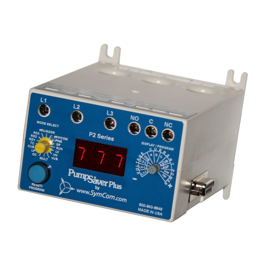
777 / 77C SERIES
Single-Phase Current & Voltage Monitor
Wiring Diagram
TYPICAL WIRING DIAGRAM FOR MODEL 77C WITH MOTOR CONTROL
TYPICAL WIRING DIAGRAM FOR MODEL 77C WITH EXTERNAL CT
LITTELFUSE RECOMMENDS USING CTs THAT HAVE TERMINALS
TO AID CONVENIENCE WHEN INSTALLING CTs.
NOTE: PHASES A & C ARE INACTIVE. USE PHASE B FOR ALL ACTIVE
CURRENT MEASUREMENTS. CT SECONDARY MUST MAKE FIVE
PASSES THROUGH THE PHASE B CONDUCTOR WINDOW.
© 2016 Littelfuse Protection Relays & Controls
www.littelfuse.com/777-77c
Description
The 777/ 77C is a fully programmable electronic overload
relay designed to protect any motor drawing 2-800 full load
amps (external CTs are required above 90 amps). Common
applications include conveyor systems, HVAC equipment, saws
and grinders, fan motors, and almost any pumping application.
All of the overload relays provide unsurpassed protection by
combining overload, underload, and voltage in one package.
For standalone applications, the units incorporate a 3-digit
LED display that is used for programming, providing real-time
operational information and displaying diagnostic codes to aid
in troubleshooting a fault condition. The units also feature a
communications port that can be used with communication
modules listed in the 777 accessories section to form a
Modbus, DeviceNet™, Profibus, or Ethernet network. Up to
99 units can be remotely monitored and controlled from a PC,
PLC, or SCADA system, and data logging through a PC with
the optional Solutions software. This capability allows for a
simple, cost-effective way to meet new requirements for
arc-flash safety.
Features & Benefits
Ordering Information
A
B
C
FEATURES
BENEFITS
Visual indication for programming, viewing real-time
Built-in display
voltage or current, and last fault code
Programmable voltage
Allows usage on wide range of systems
and current settings
Choose from automatic, semi-automatic, or manual to
3 selectable
restart options
best meet individual application needs
Program separate restart delay time for rapid cycle
3 programmable restart
delay timers
protection, motor cool down, and dry-well recovery
Increases safety through remote display of real-time
Remote display
data and fault history, without the need to open the
compatibility
cabinet. Aids with arc flash safety regulations
Reset can be done through pushbutton on relay or
Flexible reset
remotely with optional 777-MRSW or OL-RESET
remote reset kit
Network
Compatible with Modbus, DeviceNet™, Profibus, or
communications
Ethernet using optional communications module
capability
MOTOR FULL
MODEL
LINE VOLTAGE
AMP RANGE
2-800A (external
77C
100-240VAC
CTs required
above 90A)
77C-LR
100-240VAC
1-9A only
2-800A (external
777-
340-480VAC
CTs required
HVR-SP
above 90A)
DESCRIPTION
Provides 480VA @ 240VAC
output SPDT relay contacts
Provides 480VA @ 240VAC
output SPDT relay contacts
Provides 470VA @ 600VAC
output SPDT relay contacts.
For systems with no control
power transformer
Rev: 1-A-062816
Advertisement

Related Manuals for Littelfuse 777 Series

Summary of Contents for Littelfuse 777 Series
- Page 1 Flexible reset remotely with optional 777-MRSW or OL-RESET TYPICAL WIRING DIAGRAM FOR MODEL 77C WITH EXTERNAL CT remote reset kit LITTELFUSE RECOMMENDS USING CTs THAT HAVE TERMINALS Network Compatible with Modbus, DeviceNet™, Profibus, or TO AID CONVENIENCE WHEN INSTALLING CTs.
- Page 2 H 77.47 mm (3.05”); W 97.79 mm (3.85”); D 128.27 mm (5.05”) Weight 1.56 lbs. (24.96 oz., 707.6 g) Mounting Method Surface mount (4 - #8 screws) or DIN rail mount © 2016 Littelfuse Protection Relays & Controls Rev: 1-A-062816 www.littelfuse.com/777-77c...