Littelfuse MP8000 Instruction Manual
Motor protection relay
Hide thumbs
Also See for MP8000:
- Quick start manual (2 pages) ,
- Faq (9 pages) ,
- Instruction manual (44 pages)

Related Manuals for Littelfuse MP8000


Summary of Contents for Littelfuse MP8000
- Page 1 Tel: +1-800-832-3873 E-mail: techline@littelfuse.com www.littelfuse.com/mp8000 MP8000 MOTOR PROTECTION RELAY Instruction Manual REVISION 0-A-030818 Copyright © 2018 Littelfuse. All rights reserved.
- Page 2 The information in this document is provided for informational use only and is subject to change without notice. Littelfuse, Inc. has approved only the English language document. This product is covered by the standard Littelfuse 5-year warranty. For warranty details, visit www.littelfuse.com or contact your customer service representative.
-
Page 3: Table Of Contents
(Z1, Z2) (for Ground Fault detection) ......16 1.3 General Information .............4 3.5.12 Connecting to a PC ..........16 1.3.1 Typographic Conventions .........4 3.5.13 Connecting to the Littelfuse MP8000 App ....16 1.3.2 Examples ..............4 3.6 AC/DC Control Connection Diagrams ........16 1.3.3 Product Labels ............4 3.6.1 Three-Phase Motor under 100 FLA with... - Page 4 Page 2 MP8000 Motor Protection Relay REV. 0-A-030818 SECTION PAGE SECTION PAGE 4.8.14 Hardware Configuration Fields 4.9.7 Line Current ............27 Single-Phase Motor (SPM) ........25 4.9.8 Current Unbalance ..........27 4.8.15 Communication Settings ........26 4.9.9 Power ..............27 4.8.16 RTD Module ............26 4.9.10 Power Factor ............27 4.8.17 Change Device Name ..........26...
-
Page 5: Preface
Indicates a potentially hazardous situation that, if not CAUTION 3. INSTALLATION avoided, could result in death or serious injury. Refer to accompanying documents. Protective earth (ground) Describes how to mount and wire the MP8000; illustrates wiring connections for various applications. Earth (ground) CAUTION NOTE: Direct current 4. -
Page 6: Warnings, Cautions, And Notes
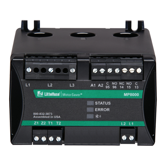
1.3.3 Product Labels can result if you do not use proper ESD procedures. The MP8000 label is shown below. The label is located Ground yourself, your work surface, and this equipment Instruction manual on the right side panel of the product. -
Page 7: Introduction And Specifications
• Current: Built-in pass-through current transformers This manual contains the information needed to install, for 0.5-100A phase current measurements set, test, operate, and maintain any MP8000. You need not review the entire manual to perform specific tasks. • External current transformer inputs for >100A... -
Page 8: Applications
• With or without external current and/or voltage transformer • Full voltage non-reversing (FVNR) starter (across the line) • Forward/reverse starter – Accomplished by placing the MP8000 “above” the forward and reverse contactors. PHASE A PHASE B 90 - 690 VAC 0.5 - 100A (100A+ using external CTs) -
Page 9: Getting Started
IEC 60947-1 Edition 5.2 (UL 60947), This section presents the fundamental knowledge IEC 60947-8-1, EC 60947-4-1 you need to operate the MP8000, organized by task. UL, cUL: UL-1053, C.22.2 No. 14 These tasks help you become familiar with the relay... -
Page 10: Type Tests
Page 8 MP8000 Motor Protection Relay REV. 0-A-030818 Optoisolated Control Inputs Operating Environment (Externally Wetted to 110/240 VAC) Pollution Degree: Maximum Current Draw: 5 mA @ 110 VAC, 10 mA @ 240 VAC Overvoltage Category: III (up to 300 VAC to earth) -
Page 11: Current Transformers (Cts)
5 seconds 2.6.5 Relay Elements CUB setting + 6% 4 seconds See section Littelfuse MP8000 Smartphone and Tablet App > CUB setting + 10% 3 seconds Configuration Page for details on programming relay behavior. CUB setting + 15% or more... - Page 12 Page 10 MP8000 Motor Protection Relay REV. 0-A-030818 Incomplete Sequence (Load Jam/Stall) (48) Ground Fault - Residual Method (Zero-Sequence)(50N) Parameter Name: Stall Percentage Current (STLP) Best protection is with a resistively grounded system Enable/Disable: Default is disabled Parameter Name: Ground Fault Trip Current (GFTC) Setting Range: Not limited;...
-
Page 13: Metering
Page 11 MP8000 Motor Protection Relay REV. 0-A-030818 Inverse-Time Overcurrent (51) 2.6.6 Metering Accuracies are specified at 20°C, 50 or 60 Hz nominal frequency, Parameter Name: Trip Class (TC) AC currents within 0.5 – 100 A , and ac voltages within... -
Page 14: Installation
REV. 0-A-030818 3. INSTALLATION Overview Relay Placement The first steps in applying the MP8000 Motor Proper placement of the MP8000 helps to ensure Protection Relay are installing and connecting the years of trouble-free motor management. Use the relay. This section describes common installation following guidelines for proper physical installation of features and requirements. -
Page 15: Relay Mounted On Din Rail
3.4.1 Relay Mounted on DIN Rail The MP8000 can be mounted on a 35 mm (1.38 in) DIN rail. Install the relay on the DIN rail as shown in Figure 3.3 and push the relay towards the rail until the bottom clip latches and the relay clicks into place. -
Page 16: Relay Mounted On Solid Surface Or Panel
Page 14 MP8000 Motor Protection Relay REV. 0-A-030818 3.4.2 Relay Mounted on Solid Surface or Panel The drawing in Figure 3.4 shows how the relay is mounted on a panel or a flat surface. The screws are #8 or 4 mm and the tightening torque specification is 9.0 in-lbs (1.0 Nm). -
Page 17: Power Supply Connections (A1, A2)
In this configuration the CT number reflects the number of passes through the window the wires have • The relay coil is also de-energized if the MP8000 power been ‘looped’. Example: 5 passes of each conductor supply voltage is removed or if the MP8000 fails. -
Page 18: Ptc Connections (T1, T2)
The maximum length of the Phase A motor power wire must pass through the twisted pair of wires from the ZSCT to the MP8000 Phase A "window" (hole). It must pass through the relay terminals Z1, Z2 should be limited to 5 feet or window with the power source (side with the letter less and currently limited to 100A zero-sequence CTs. -
Page 19: Three-Phase Motor Over 100 Fla
Page 17 MP8000 Motor Protection Relay REV. 0-A-030818 3.6.2 Three-Phase Motor over 100 FLA NOTE: CT ratio must be changed to accommodate the Refer to Figure 2.1 for all voltage and control wiring. CT ratio used. Example: a CT ratio of 200:5, program Refer to Figure 3.6 for external current transformer... -
Page 20: Single-Phase Applications
Page 18 MP8000 Motor Protection Relay REV. 0-A-030818 3.6.3 Single-Phase Applications Refer to Figure 3.7 for single-phase motor applications. Refer to Sections 4.7 and 4.8 for all settings. PHASE A 90 - 690 VAC PHASE B 0.5 - 100A FROM A1... -
Page 21: Littelfuse Mp8000 Smartphone And Tablet App
After you have installed the Littelfuse MP8000 App, application. We will refer to app screens or displays as a Littelfuse icon should be visible on one of your app pages. All pages are scrollable. pages. See Figure 4.2. Touching the icon starts the app. -
Page 22: Configuration
Figure 4.3 Advertising page Figure 4.5 Automated Configuration request Select the MP8000 you would like to view. If it is the If cancel is chosen you will return to the Advertising first time that this smartphone or tablet has accessed page. -
Page 23: Configuration Basic Page (Protective Features)
The Littelfuse MP8000 app ensures that the value authorization credentials will be requested. The factory you provided was successfully programmed into default password is unique to each MP8000 and is the MP8000 and renders a message affirming the located on the side adhesive label and on additional modification. -
Page 24: High Voltage (Hv)
Example: Nameplate voltage = 230 V 4.7.7 Trip Class (TC) Determines how quickly the MP8000 will trip when an HV = 110% x 230 = 253 V overcurrent (overload) condition is detected. 4.7.3 Voltage Unbalance (VUB) The standard trip classes are 5, 10, 15, 20, and 30. -
Page 25: Restart Delay One (Rd1)
If RF is set to “0” , the MP8000 will require manual reset after tripping on OC, CUB, or HKW. Table 4.3 Common CT Ratios and CT Setting... -
Page 26: Potential Transformer Ratio (Pt)
PT ratio used. Example: a PT ratio of 4160:120, The maximum allowable current that can flow to program 35 for PT. ground before the MP8000 trips or alarms. See GFMT Table 4.4 Common PT Ratios and PT Setting Section 4.8.14 for configuration of trip or alarms. This is... -
Page 27: High Power Trip Delay (Hptd)
See Figure 4.10, the (a) This parameter is the time that the jam/stall condition drawing for the PT connections. must be present before the MP8000 trips on overcurrent. PTC Enable (PTC) 4.8.12 Stall Inhibit Delay (STID) -
Page 28: Communication Settings
System Status this process. This field displays the status of the relay. Hold-off and trip conditions are displayed here. 4. Ensure that the LEDs on the front of the MP8000 are visible. 4.9.4 Active Timer If any delay timer is active, the remaining time is 5. -
Page 29: Line-To-Line Voltage
Page 27 MP8000 Motor Protection Relay REV. 0-A-030818 4.9.14 Fault Page The main Fault page is scrollable and lists up to 1,000 faults with the most recent faults first. See Figure 4.12. Figure 4.11 Real-Time Page 4.9.5 Line-to-Line Voltage The input voltages, L1, L2, and L3, are measured and displayed as line-to-line RMS AC voltages. -
Page 30: Time Settings
DHCP server or to a network that does not have a DHCP server available, then the MP8000 will assign itself its own IP address based on its MAC address. Each MP8000 MAC address is defined with the... - Page 31 MP8000’s IP Address. The IP address is needed to open the MP8x00 Configuration Web site. The IP address is shown in the MP8000 Software Device Info tab selection: Figure 4.17 MP8x00 Configuration Web Page – Select Change IP Address Figure 4.15...
- Page 32 Note: Follow each step of this process. On completing the write to the RD3 Dry Well Recovery Timer, all fields will be returned to their original state and the MP8000 will change its IP address to the assigned value. Also, if the assigned address is: 255.255.255.255 the MP8000 will use DHCP assignment.
-
Page 33: Pc Interface
The MP8000 Software runs on Windows 7 or higher. for information regarding memory maps, commands, The user can select an MP8000 unit from a list on and all information for writing custom interfaces. the left panel of the screen. That unit's parameters will be displayed in the right panel. -
Page 34: Troubleshooting
The voltage inputs are reverse-phased. If this is the initial start-up, there are two solutions. Either "Enable ACB Phase Rotation" in advanced settings in the Littelfuse MP8000 app, or swap any two of the leads connected to L1, L2, or L3 Reverse-Phased on the MP8000 to correct the problem. -
Page 35: Ground Fault Testing Procedure
REV. 0-A-030818 7. GROUND FAULT TESTING PROCEDURE A ground fault test must be performed before installing the MP8000 as required by UL1053 and NEC, ANSI/NFPA 70. 1. Disconnect power. 5. The values of V and R will be determined by the current required to generate a GF trip condition: 2.
Need help?
Do you have a question about the MP8000 and is the answer not in the manual?
Questions and answers