Table of Contents
Advertisement
Mounting Instructions
Multipole Conductor Rail System
Program 0831
Order Number
0831xx-...
Contents
1
System description ...................................................................................................................................................................... 2
2
Intended use ............................................................................................................................................................................... 3
3
Control components .................................................................................................................................................................... 4
4
Assembly .................................................................................................................................................................................... 5
4.1
Adjusting the lengths ................................................................................................................................................... 7
4.2
Installation of the fixed point and the hanger clamp .................................................................................................... 8
4.2.1
Fixed point ................................................................................................................................................................... 8
4.2.2
Hanger clamps ............................................................................................................................................................ 9
4.2.3
(Optional) safety catching device .............................................................................................................................. 12
4.3
Click the conductor rail into its place ......................................................................................................................... 13
4.4
Position of the end and center feeds ......................................................................................................................... 14
4.5
Connect the conductor rail ......................................................................................................................................... 15
4.6
Remedy in case of damaged connecting pins ........................................................................................................... 22
5
Installation of expansion elements ............................................................................................................................................ 23
6
Assembly of the current collectors ............................................................................................................................................ 25
7
Screw tightening torques .......................................................................................................................................................... 27
8
Index ......................................................................................................................................................................................... 28
9
Index of the animations ............................................................................................................................................................. 32
MV0831-0006e-EN
www.conductix.com
translated document
Page 1 of 32
Advertisement
Table of Contents

Related Manuals for Delachaux Conductix Wampfler 0831


Summary of Contents for Delachaux Conductix Wampfler 0831
-
Page 1: Table Of Contents
Mounting Instructions Multipole Conductor Rail System Program 0831 Order Number 0831xx-… Contents System description ..................................2 Intended use ....................................3 Control components ..................................4 Assembly ....................................5 Adjusting the lengths ..............................7 Installation of the fixed point and the hanger clamp ....................8 4.2.1 Fixed point ................................... -
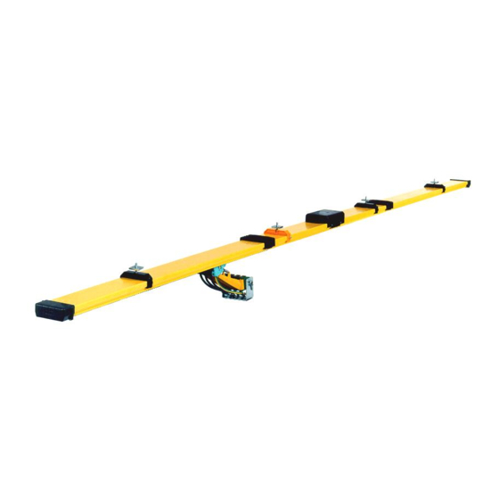
Page 2: System Description
Mounting Instructions Multipole Conductor Rail System Program 0831 1 System description Fig. 1: Components of the multipole conductor rail system program 0831 Item Designation Conductor rail Hanger clamp Fixed point Centre feed End cap Current collector Towing unit Connector See chapter 8 for other components of the multipole conductor rail system. MV0831-0006e-EN www.conductix.com translated document... -
Page 3: Intended Use
Mounting Instructions Multipole Conductor Rail System Program 0831 2 Intended use The multipole conductor rail system serves for the energy and data transmission on indoor systems and weatherproof outdoor systems on straight travel paths. Possible fields of application: Storage and retrieval equipment ... -
Page 4: Control Components
Mounting Instructions Multipole Conductor Rail System Program 0831 3 Control components Prior to mounting check the goods (consisting of several packages) for completeness and damage by means of the delivery note: Ensure that all required packages are on site. The conductor rails are available with various nominal values and of various conductor materials: Strength of the conductor Conductor material... -
Page 5: Assembly
Mounting Instructions Multipole Conductor Rail System Program 0831 4 Assembly The system sketch shows the mounting distances to the connectors and end and center feed: Fig. 3: System sketch See Fig 5 for suspension distance (x) and center distance (y) Item Designation End cap or end feed (not illustrated) - Page 6 Mounting Instructions Multipole Conductor Rail System Program 0831 code („click“ „scan“), watch animation MultiLine 0831 Overview code („click“ „scan“), watch animation Console Assembly code („click“ „scan“), watch animation Console Aligning MV0831-0006e-EN www.conductix.com translated document Page 6 of 32...
-
Page 7: Adjusting The Lengths
Mounting Instructions Multipole Conductor Rail System Program 0831 4.1 Adjusting the lengths The multipole conductor rail systems are supplied by standard in lengths of 4000 mm, 3000 mm, 2000 mm and 1000 mm. All kinds of system lengths can thus be realized. ... -
Page 8: Installation Of The Fixed Point And The Hanger Clamp
Mounting Instructions Multipole Conductor Rail System Program 0831 4.2 Installation of the fixed point and the hanger clamp 4.2.1 Fixed point The fixed point secures the multipole conductor rail system against displacement. The fixed point consists of an orange hanger clamp and a self-tapping screw. -
Page 9: Hanger Clamps
Mounting Instructions Multipole Conductor Rail System Program 0831 4.2.2 Hanger clamps The hanger clamps are designed as sliding suspensions (see Fig. 3): Suspension distance x Center distance y System length 50.000 mm System length > 50.000 mm 1000 mm 190 10 mm 320 10 mm Fig 5: Dimensions of the suspension distance and the center distance... - Page 10 Mounting Instructions Multipole Conductor Rail System Program 0831 Fig. 7: Distribution of hanger clamps, rail connectors and fixed points Item Designation Conductor rail Hanger clamp Connector Fixed point Max. length of track (without expansion units): Length Temperature Without expansion units On systems with lengths L ≤...
- Page 11 Mounting Instructions Multipole Conductor Rail System Program 0831 code („click“ „scan“), watch animation Hanger Clamp and Anchor Point Assembly (horizontal operation) code („click“ „scan“), watch animation Hanger Clamp and Anchor Point Assembly (vertical operation) MV0831-0006e-EN www.conductix.com translated document Page 11 of 32...
-
Page 12: Optional) Safety Catching Device
Mounting Instructions Multipole Conductor Rail System Program 0831 4.2.3 (Optional) safety catching device The conductor rail is equipped with a catching clip including catch-rope, if the installation height is more than 3.000 mm or there is an increased risk potential. In the event of a collision or another damaging event the multipole conductor rail system will be secured by the catch-rope at the framework of the supporting construction. -
Page 13: Click The Conductor Rail Into Its Place
Mounting Instructions Multipole Conductor Rail System Program 0831 4.3 Click the conductor rail into its place Observe the alignment of the conductor rail. Click the conductor rail into the hanger clamp. In a vertical arrangement the clip must point upward (see Fig. 6)! CAUTION! Fig. -
Page 14: Position Of The End And Center Feeds
Mounting Instructions Multipole Conductor Rail System Program 0831 4.4 Position of the end and center feeds The position of the end and center feeds is specified by the connecting points on site. The alignment of the end and center feed, among others, determines the position of the protective earth conductor. -
Page 15: Connect The Conductor Rail
Mounting Instructions Multipole Conductor Rail System Program 0831 4.5 Connect the conductor rail Prerequisites: The hanger clamps are mounted as in chapter 4. The conductor rails that are to be connected must be completely clicked into the hanger clamps. ... - Page 16 Mounting Instructions Multipole Conductor Rail System Program 0831 Fig. 13: Detailed view socket side Fig. 14: Detailed view pin side Item Designation Insulating profile Connector cap Cross-head screw Socket Pin side Connecting clamp Conductor rail (conductor) Connecting pin with spring element Stop position of the connecting pin MV0831-0006e-EN www.conductix.com...
- Page 17 Mounting Instructions Multipole Conductor Rail System Program 0831 Prior to making a rail connection, check if connecting pin and socket are in perfect condition! On the pin side it must be checked if: CAUTION! Connecting pins and connecting clamps are existing and in the same position (see Fig. 10, item 1 ...
- Page 18 Mounting Instructions Multipole Conductor Rail System Program 0831 Working steps: The assembly always starts at one end of the multipole conductor rail systems and not in the center: Click the first conductor rail into the hanger clamp in such a way that the pin end is the end (or the beginning) of the multipole conductor rail system.
- Page 19 Mounting Instructions Multipole Conductor Rail System Program 0831 There are 2 different possibilities to make a plug and socket connection: Push the connector side manually over the open rail end until it stops (see Fig. 15). Place the mounting block next to the socket side of the conductor rail to be mounted.
- Page 20 Mounting Instructions Multipole Conductor Rail System Program 0831 A gap between the conductors is non-critical! Conductor material and plastic profile have different coefficients of expansion. By pre-assembly the conductor material is 2 mm shorter than the insulating profile (temperature 20°C), to compensate for CAUTION! the expansion.
- Page 21 Mounting Instructions Multipole Conductor Rail System Program 0831 Fig. 23: Secure end cap Carry out the installation of the complete multipole conductor rail system in this way. code („click“ „scan“), watch animation End Caps Assembly MV0831-0006e-EN www.conductix.com translated document Page 21 of 32...
-
Page 22: Remedy In Case Of Damaged Connecting Pins
Mounting Instructions Multipole Conductor Rail System Program 0831 4.6 Remedy in case of damaged connecting pins The connecting pin has a stop device and is inserted up to the middle on pre-assembly. If 1 connecting pin has been pushed in further during transport, it must be pulled back to its middle position. ... -
Page 23: Installation Of Expansion Elements
Mounting Instructions Multipole Conductor Rail System Program 0831 5 Installation of expansion elements On multipole conductor rail systems with a length 200.000 mm and if the fluctuation of the ambient temperature (T) during operation is more than 20 °C, expansion elements will be arranged. ΔT [°C] a [mm] 11.000... - Page 24 Mounting Instructions Multipole Conductor Rail System Program 0831 Diagram for the determination of the air gap setting [°C] = Ambient temperature [mm] = Air gap Fig. 25: Determination of the air gap setting: Example: Min. ambient temperature during system operation: 5°C Temperature during installation: 15°C...
-
Page 25: Assembly Of The Current Collectors
Mounting Instructions Multipole Conductor Rail System Program 0831 6 Assembly of the current collectors Install the current collectors according to the sketch. A and B = Functional dimensions (distance to the conductor rail running surface) Fig. 26: Current collectors in horizontal arrangement/vertical engagement Item Designation Conductor rail running surface... - Page 26 Mounting Instructions Multipole Conductor Rail System Program 0831 Arrangement/engagement Features Mount the central axis of the central current collector exactly onto the Horizontal arrangement/vertical engagement central axis of the appropriate conductor rail. Install the lowest current collector in parallel to the corresponding Vertical arrangement/horizontal engagement conductor rail.
-
Page 27: Screw Tightening Torques
Mounting Instructions Multipole Conductor Rail System Program 0831 7 Screw tightening torques Screws Relevant components M6 [Nm] M8 [Nm] Additional information End and center feed max. 10 max. 25 Hanger clamps Fixed point Connector screw in (flush) until it stops End cap/end cap for passages See „KAT0831-0001-E“... -
Page 28: Index
Mounting Instructions Multipole Conductor Rail System Program 0831 8 Index 083143-...; hanger clamp 083145-...; hanger clamp with steel nut for C-rail assembly 083133-...; anchor clamp with steel nut 083135-...; anchor clamp for C-rail assembly 083171-...; 083172-...; 083195-...; end cap end cap for passages air gap insulation section MV0831-0006e-EN www.conductix.com... - Page 29 Mounting Instructions Multipole Conductor Rail System Program 0831 0831XX-...; conductor rails (pin side) 083181-...; pick-up guide for passages 083151-...; 083154-...; 083152-...; center feed (max. 10 mm²) center feed (max. 35 mm²) center feed (max. 35 mm²) 083153-...; 083161-...; center feed (max. 35 mm²) expansion element MV0831-0006e-EN www.conductix.com...
- Page 30 Mounting Instructions Multipole Conductor Rail System Program 0831 083106-...; 083103-...; current collector unit 081050-...; current collector for 80 A for 55 A per pole towing bracket 081001-...; 083103-...; collector brush for 80 A (spare part) current collector unit for 55 A per pole with terminal box 08-S280-0613 Safety catching device for horizontal assembly and installation height >...
- Page 31 Mounting Instructions Multipole Conductor Rail System Program 0831 Mounting block 3-pole Mounting block 4-pole Mounting block 5-pole 08-V015-0492-003 08-V015-0492-004 08-V015-0492-005 MV0831-0006e-EN www.conductix.com translated document Page 31 of 32...
-
Page 32: Index Of The Animations
Mounting Instructions Multipole Conductor Rail System Program 0831 9 Index of the animations Please click the hyperlink or scan the code to start each animation: MultiLine 0831 Overview: MOV0831-0001 Console Assembly: MOV0800-0002 Console Aligning: MOV0800-0003 Hanger Clamp and Anchor Point Assembly MOV0831-0002 (horizontal operation): Hanger Clamp and Anchor Point Assembly...
Need help?
Do you have a question about the Conductix Wampfler 0831 and is the answer not in the manual?
Questions and answers