
Related Manuals for RFI G-router


Summary of Contents for RFI G-router
- Page 1 G-router GSM/GPRS to RS-232 and Ethernet Gateway Quick Installation Guide Author RFI Support Team Revision Quick Install Guide Version QIG_G-router_1.2.2 Date 12-01-2012 Covering Product code G-router, RE.40.QGSM...
-
Page 2: Table Of Contents
Contents Introduction ......................4 Check Your Package Contents ................5 Connectors and status LEDs on the G-router Unit ............6 Ethernet and 802.3af (Power over Ethernet) Pin Assignments ......... 7 RS-232 Pin Assignments ................... 7 Relay connections.................... 8 Installation Overview ..................... 9 Inserting the SIM card .................. - Page 3 The information contained in this document is subject to change. This document contains proprietary information, which is protected by copyright laws. All rights are reserved. No part of this document may be photocopied, reproduced or translated to another language or program language without prior written consent of RFI Engineering B.V. QIG_G-router_1.2.2 Page: 3(21)
-
Page 4: Introduction
The optional remote power switch can be used for an effective reboot of the connected equipment. The G-router can be customized to optimally suit customer requirements to provide a reliable competitive solution for wireless M2M projects. The GSM/GRPS unit can be used in combination... -
Page 5: Check Your Package Contents
1.1 Check Your Package Contents These are the items included with your G-router purchase: 1x G-router GSM/GPRS unit 1x PoE Power Supply unit Mains Power cables (optional) Dependent on the territory different power supplies will have to be used. In Europe a European style 220V/AC power cable can be supplied as optional. -
Page 6: Connectors And Status Leds On The G-Router Unit
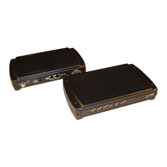
2 Connectors and status LEDs on the G-router Unit This section provides an overview of the connectors and status LEDS on the G-router unit. Figure 1: G-router front view Blue, Power LED Green, Modem Green, Status. Flashing when unit is booting Green, Call. -
Page 7: Ethernet And 802.3Af (Power Over Ethernet) Pin Assignments
2.1 Ethernet and 802.3af (Power over Ethernet) Pin Assignments 2.2 RS-232 Pin Assignments The following signals are internally connected in the RS-232 port on the G-router unit: Carrier Detect (pin 1), Data Terminal Ready (pin 4) and Data Set Ready (pin 6) •... -
Page 8: Relay Connections
2.3 Relay connections The G-router has a low power relay contact that can be used for remote controlling low power devices. In order to connect the relay contact to the low power device you can use a cable with an RJ-11 connector. The two middle pins (pin 3 and 4) of the RJ-11 connector are connected to the relay, whereby the relay is normally open. -
Page 9: Installation Overview
G-router. Please see paragraph 5.4 for retrieving the GSM status. 3.1 Inserting the SIM card In order to start using the G-router you need to insert a miniature SIM card. Please make sure the SIM card is a data card and the mobile network operator supports CSD. The SIM card holder is located inside to the G-router and can only be accessed by unscrewing the four screws in the bottom of the unit. -
Page 10: Connecting The G-Router Unit To Your Network
3.2 Connecting the G-router Unit to your network A. Connect an Ethernet cable to the port labeled “Eth0(POE)” on the RFI G-router. B. Connect the other end of the Ethernet cable to the port labeled “J1 Data & PWR” on the Power-over-Ethernet (PoE) power supply. -
Page 11: Accessing The G-Router Configuration, User 'Admin
PC. When the G-router ships, the unit has been configured with a fixed IP address. In order to log in to the G-router you can connect a laptop or desktop computer to the Ethernet port of the unit. In case you connect a computer directly to the G-router please make sure you use a cross Ethernet cable. -
Page 12: Logging Out (Cli)
CLI you are automatically logged out. Changing your password (CLI) The G-router ships with the default password rfi123. It is advisable to change this password when the system is installed. The password for the various users can be changed through the ‘Users’... - Page 13 Go down to General -> Reboot and press [ENTER] to reboot the G-router. Figure 5: changing the password for user: admin through the CLI The information contained in this document is subject to change. This document contains proprietary information, which is protected by copyright laws.
-
Page 14: Console Login Via Browser And The Ethernet Port (Web)
To connect to your G-router using a standard web browser, start the web browser and enter the IP address of the G-router in the address bar. The G-router will ask for a user name and password. Enter user: ‘admin’ and password: ‘rfi123’. Once logged in the G-router presents the... -
Page 15: Console Login Via Gsm Dial-In
During normal operation the G-router connects the GSM modem directly to the RS-232 port on the back of the G-router unit. For this example we assume that the G-router is connected to the console port of the (Cisco) WAN router as shown in Figure 3. Dialing in to the unit connects the dial-in session directly to the console port of the Cisco router. -
Page 16: Disconnect The Gsm Dial-In Connection
The information contained in this document is subject to change. This document contains proprietary information, which is protected by copyright laws. All rights are reserved. No part of this document may be photocopied, reproduced or translated to another language or program language without prior written consent of RFI Engineering B.V. Page: 16(21) -
Page 17: Advanced Configuration, User 'Root
1 00:00 `- alias The setting of configuration elements is done through the HIB client by giving the command “hibc set”. For example to set the IP address of the G-router you would give the following command: hibc set config/network/eth0/ip_method/static/ip_address "192.168.168.1"... -
Page 18: Retrieving The Gsm Configuration
PIN code settings. Only when the SIM card has the PIN code option enabled will the G-router attempt to enter the PIN code. The unit will only attempt once to log in with the PIN code to prevent accidentally blocking the SIM card when a wrong PIN code has been entered. -
Page 19: Setting Idle-Timer Timeout
5.5 Setting idle-timer timeout The G-router is equipped with a configurable idle timer. This idle timer disconnects the GSM call when there is no data being received from the remote (dialer) end. The factory default setting for this timer is 300 seconds (5 minutes). -
Page 20: Led Status And Patterns Of The G-Router
Green, GPRS status Green, Contact/Relay status 6.1 Power LED The blue power LED is hardwired to the power supply of the G-router and should always be lit when the unit is in operation. 6.2 Modem status LED The green modem status LED indicates the current status of the G24 Motorola modem which is part of the G-router. -
Page 21: Call Status Led
GSM operator. When there is no GPRS coverage possible the LED will be off. 6.6 Relay status LED The G-router already has a relay status LED but NO relay contact is present in the current hardware. Please note that the relay itself will be placed upon the following release of the hardware.
Need help?
Do you have a question about the G-router and is the answer not in the manual?
Questions and answers