Table of Contents
Advertisement
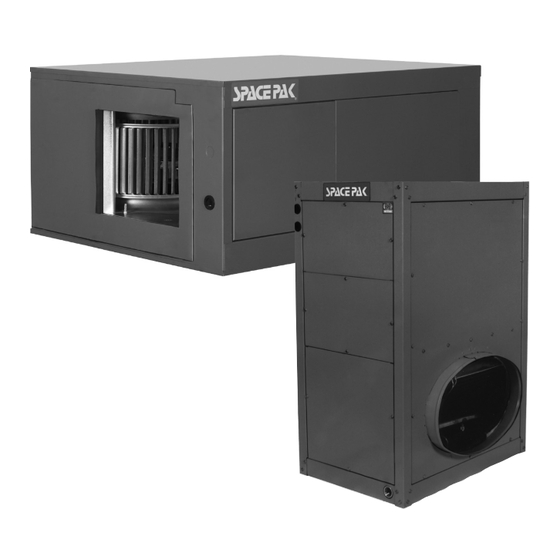
MODELS WCSPJ &
WCSP-JV
INSTALLATION,
OPERATION
& MAINTENANCE
MANUAL
Central Hydronic Coil Series
2 to 5 Tons
Fan Coil Unit/Air Supply
Components
SpacePak System Design .......................................2
Code Compliance ....................................................2
Air Distribution Requirements ..................................2
Model Number Description ......................................2
Air Distribution Components ....................................3
Shipment of Unit ......................................................5
Step 1: Locating The Unit ........................................5
Step 2: Cutting Return Air Opening .......................10
Step 3: Attaching Supply Air Plenum Adaptor ....... 11
Step 4: Setting The Unit ........................................12
Step 5: Connecting Water Lines ............................13
Step 7: Wiring The Unit .........................................14
Step 9: B & C Series Unit Retrofits ........................20
IN UNITED STATES: 260 NORTH ELM ST. WESTFIELD, MA 01085 800-465-8558 / FAX (413) 564-5815
IN CANADA: 7555 TRANMERE DRIVE, MISSISSAUGA, ONTARIO, L5S 1L4 (905) 670-5888 / FAX (905) 670-5782
Controls Overview .................................................23
System Menu.........................................................26
Factors Affecting the Balance of the System .........29
System Commissioning .........................................30
Before Each Cooling Season ..................................... 30
If System Fails To Operate ....................................30
Service/Troubleshooting Form ..............................31
Parts List...........................................................32,33
Warranty ................................................................34
WCSPJ2-0420
45W30-WG1284
Advertisement
Table of Contents

Related Manuals for SpacePak WCSPJ Series


Summary of Contents for SpacePak WCSPJ Series
-
Page 1: Table Of Contents
2 to 5 Tons Fan Coil Unit/Air Supply Components SECTION 1: INTRODUCTION SECTION 3: START UP & COMMISSIONING SpacePak System Design ........2 Controls Overview ..........23 Code Compliance ............2 System Menu............26 Air Distribution Requirements ........2 Factors Affecting the Balance of the System ..29 Model Number Description ........2... -
Page 2: Section 1: Introduction
COMPONENT REQUIREMENTS SPACEPAK SYSTEM DESIGN Air distribution components installation must conform The SpacePak WCSP-J V unit is a hydronic fan coil unit to the requirements of local authority having jurisdiction which utilizes chilled or heated water from a chiller or... -
Page 3: Air Distribution Components
FIGURE 1.1: AIR DISTRIBUTION SYSTEM COMPONENTS Part Number Description Horizontal Vertical SPC-1D Return Air Box for unit size 2430. Includes filter grill with metal frame, permanent filter, and 2 clamp bands. AC-RBF-3 Return Air Box for unit size 3642. Includes filter grill with metal frame, permanent filter, and 2 clamp bands. SPC-3D Return Air Box for unit size 4860. - Page 4 Plenum Duct For systems with a bullhead tee installed as on Unit No. The plenum duct can be run in practically any location 1 (Figure 1.3), the best results are obtained if not more accessible for the attachment of the supply tubing (see than 60% of the total number of system outlets are suggested layouts in Figure 1.2).
-
Page 5: Shipment Of Unit
Supply Tubing FIGURE 1.4: TERMINATOR IN SOFFIT AREA In the case of two-story or split-level applications, supply tubing may run from one story to another. It is small enough to go in stud spaces, but this is often difficult in older homes because of hidden obstructions in stud spaces. - Page 6 FIGURE 2.1: MODEL WCSP-J DIMENSIONS AND CLEARANCES - (In Inches) FIGURE 2.2: MODEL WCSP SPECIFICATIONS Connections System Bottom Cond. Return capacity Electrical Water Water Drain Inlet Model (Nom. Tons) Characteristics* (NPT) (Dia.) WCSP-2430J 2 - 2-1/2 230/1/60 7/8" 7/8" 3/4" 15"...
- Page 7 FIGURE 2.3: UNIT DIMENSIONS AND CLEARANCES SUPPLY AIR OPENING 230VAC [965] [305] MIN. CLEARANCE MIN. CLEARANCE LOW VOLTAGE Ø7/8 O.D. (WATER OUT) 3/4 NPT DRAIN CONNECTION 10 9 RETURN AIR OPENING 11 1 4 11 16 1 Ø7/8 O.D. (WATER IN) MODEL WCSP-2430 (V) 24-3/8 [619]...
- Page 8 WCSP-2430 @ 550 cfm Cooling Capacity WCSP-2430 @ 550 cfm Heating Capacity 26.0 60.0 24.0 55.0 42 EWT 22.0 50.0 160 EWT 45 EWT 45.0 20.0 40.0 140 EWT 18.0 35.0 48 EWT 16.0 30.0 120 EWT 14.0 25.0 20.0 12.0 3 .0 5 .0...
-
Page 10: Step 2: Cutting Return Air Opening
Refer to the "Installation Tip" supplied with the not install the return air box until the installation of the return air box. entire SpacePak system is completed, if you want to fit materials up through this hole. NOTICE: For horizontal units the return air adapter may need to be removed from the unit to fit through the opening cut out. -
Page 11: Step 3: Attaching Supply Air Plenum Adaptor
FIGURE 2.6: RETURN AIR BOX FRAME DIMENSIONS Measure return air box dimension "A" to determine length of opening. Height = 14-5/16" 14-5/16" DWG0045 STEP 3: ATTACHING SUPPLY AIR PLENUM ADAPTOR NOTICE: If unit is to be located in the attic and installed through the ceiling joists, attach the supply air plenum adaptor in the attic. -
Page 12: Step 4: Setting The Unit
STEP 4: SETTING THE UNIT Construct a platform for the fan coil unit, as shown in NOTICE: Leave room on sides for servicing. Figure 2.10. The platform can be constructed of 2 X 4 (minimum), 2 X 6, 2 X 8 and 2 X 10 lumber, as necessary For installations with a return air box and return air duct, to achieve sufficient height so that proper condensate set fan coil unit on the platform with the elliptical opening... -
Page 13: Step 5: Connecting Water Lines
FIGURE 2.11: MOUNTING PLATFORMS FOR VERTICAL INSTALLATIONS STEP 5: CONNECTING WATER LINES Connect water lines from outdoor chiller unit to the fan coil unit in accordance with the chiller manufacturer’s recommendations. -
Page 14: Step 6: Installing The Condensate Trap & Line
STEP 6: INSTALLING THE CONDENSATE TRAP & LINE NOTICE: It is a requirement of the International NOTICE: The secondary drain connection requires Mechanical Code (307.2.3) to install a secondary field supplied components to complete installation. drain or an auxiliary drain pan where damage to Follow local code requirements. - Page 15 FIGURE 2.13: MODEL WCSP-J WIRING SCHEMATIC ESP & WCSP 120V/230V BOILER/PUMP CONTROL ALL TEMP SENSORS 10K NTC LEAVING AIR 120VAC FIELD CONVERSION SENSOR EXTERNAL COIL (IF INSTALLED) SENSOR PRIMARY COIL SENSOR PRESSURE 240V B- A+ 120V L1 PRIMARY 120VAC PRIMARY 240VAC 24VAC TEMPERATURE MOTOR CONTROL...
-
Page 16: Step 8: Installing Air Distribution Components
Figure 2.14). The result would be unacceptable noise. Plenum Duct Installation OPTION: Using a SpacePak Kwik Connect Wall All tees, elbows and branch runs must be a minimum of Elbow (Model Number: AC-KCWE) addresses this condition (see Figure 2.15). - Page 17 Center the two spring clips on a line parallel to the Supply tubing comes in 100-foot sections (R8 tubing direction of the tubing routing from the room terminator comes in 75-foot sections and R6 tubing comes in 100- (see Figure 2.17). This is important since the weight of foot sections) and may be cut to length with a knife or the tubing will have a tendency to cause a part of the fine tooth hacksaw.
- Page 18 Hand insert the four plenum take off fasteners one at a time such that each clip reaches the GASKET interior of the duct. Using the SpacePak pliers, snap the fasteners into place until they lock in place (see Figure 2.22).
- Page 19 Return Air Box & Duct Installation Direct Mount Filter Box & Ductless Returns Remove the return air grill from the return air box and Center filter box over the eliptical flange of fan coil unit remove the air filter from the return air grill. (see Figure 2.26).
-
Page 20: Step 9: B & C Series Unit Retrofits
The 7" duct can still be utilized with a transition kit (Part NOTICE FOR ALL RETROFITS No. BM-6918) available from SpacePak. This kit will It may be necessary to add outlets to the system. The reduce the main plenum from 9" to 7" to adapt to the number of additional outlets will be dependent upon the existing 7"... - Page 21 9” Tee Handler C & D DESIGN RULES FOR RETRO- 7” RND w/40% or 50 % of Total Outlets FITTING “B&C” SERIES SPACEPAK A & B EQUIPMENT TO NEWER (D,E,F,G,J) SERIES EQUIPMENT 7” 90˚ A: Minimum distance from the air handler outlet to first tee or elbow is 18”...
- Page 22 Integral Air Handler Control The SpacePak ESP and WCSP air handlers now feature All delivered airflow and static pressure, for each a sophisticated control platform that has the ability to application, should be verified upon installation control fan speed by measuring static pressure and...
-
Page 23: Section 3: Start Up & Commissioning
SECTION 3: START-UP & COMMISSIONING Controls Overview/Features/Setpoints STANDBY Hold [ESC] 3 Sec UNIT SETTINGS MODEL SETUP SYSTEM 2430JH, 2430JV FAN SETTINGS UNIT SIZE 3642JH, 3642JV 4860JH, 4860JV ESP: HP OR AC UNIT TYPE WCS: RCC, AC, HEAT O [COOLING] DEFAULTS REVERSE VALVE B [HEATING] SEC HW COIL... - Page 24 UNIT TYPE For WCSP units For WCSP units UNIT TYPE HEAT For WCSP units UNIT TYPE UNIT TYPE REVERSE VALVE: The Reversing Valve Menu navigation is accomplished by using the buttons HEAT located to the right side of the J+ control board. [REVERSE VALVE] can be set to O [energized 1.4 REVERSE VALVE: HEAT...
- Page 25 0.39 ERV: ST PRESS ERV SP PRES FAN:CONST PRESS ST PRESS Y1 SP PRES 0.39 0.39 DFS: ST PRESS HRV SP PRES 2. FAN SETTINGS ST PRESS Y2 SP PRES 0.39 2. FAN SETTINGS For example: If FAN: CONSTANT PRESSURE 0.39 2.
-
Page 26: System Menu
FAN DELAY ON DELAY F A N FAN DELAY ON DELAY OFF DELAY The FAN OFF DELAY is always used to allow the fan to optionally run for a time after a demand has been OFF DELAY satisfied allowing time to offload the coil of any excess heat that may still be present. The FAN ON DELAY is only used if a coil sensor is in fault. - Page 27 Anti-frost fault: The primary coil has dropped below the Anti-frost temperature setpoint. Run Screen #5. WARNINGS: Line 1 shows the Model and Size. There are 10 warnings. The unit will continue to run C O O L I N G Line 2 shows the Unit type: Reverse Cycle Chiller, Heat during these warnings: A N T I F R O S T...
- Page 28 A T I N G H W C D I S A B L ERRORS: ADDITIONAL SUPPLEMENTARY FEATURES OF THE J+ CONTROL Configuration - Wiring Errors. ERRORS: The J+ Control is able to recognize wiring and The J+ control has 3 inputs that can be used to Configuration - Wiring Errors.
-
Page 29: Factors Affecting The Balance Of The System
NOTICE: The number of outlets and average length of the supply tubing has a significant effect on the over- 2" SUPPLY TUBING LENGTH ADJUSTMENT FACTOR CHART all system performance. It is highly recommended that the adjustment factors outlined in the SpacePak FACTOR 1.18 1.14 1.11... -
Page 30: System Commissioning
SECTION 4: MAINTENANCE The SpacePak system has been designed to provide 3. Check that unit condensate drain is clear and free years of trouble-free performance in normal installations. -
Page 31: Service/Troubleshooting Form
Temp: °F; Superheat: °F Equipment Data: Approximate time running before taking readings: Hrs. SPACEPAK Model # ESP / WCSP - Did you adjust the TXV? (Y/N); (If yes, explain): SPACEPAK Serial # SPACEPAK Date of Installation: Cond Unit Mfr:... -
Page 32: Parts List
FIGURE 4.1: MODEL WCSP-J GENERAL ASSEMBLY DETAIL OF INTERNAL CONTROL BOX WITH COVER REMOVED SPL-WG1292-01 = NOT SHOWN REPLACEMENT PARTS - HORIZONTAL FAN COIL UNITS ITEM PART DESCRIPTION UNIT SIZE PART NUMBER WCSP 2430J W06RWG0220-22 PRIMARY DRAIN PAN 3642J W06RWG0220-23 4860J W06RWG0220-24 2430J... - Page 33 FIGURE 4.2: WCSP-JV GENERAL ASSEMBLY DETAIL OF INTERNAL CONTROL BOX WITH COVER REMOVED = NOT SHOWN SPL-WG1294-01 REPLACEMENT PARTS - VERTICAL FAN COIL UNITS ITEM PART DESCRIPTION UNIT SIZE PART NUMBER WCSP 2430J W06RWG1012-02 PRIMARY DRAIN PAN ASSEMBLY 3642J W06RWG1012-03 4860J W06RWG1012-04 2430J...
-
Page 34: Warranty
LIMITED WARRANTY Central Air Conditioning Products The “Manufacturer” warrants to the original owner at the original installation site that the Central Air Conditioning Products (the “Product”) will be free from defects in material or workmanship for a period not to exceed one (1) year from the startup or eighteen (18) months from date of shipment from the factory, whichever occurs first. - Page 36 IN UNITED STATES: 260 NORTH ELM ST. WESTFIELD, MA 01085 800-465-8558 / FAX (413) 564-5815 IN CANADA: 7555 TRANMERE DRIVE, MISSISSAUGA, ONTARIO, L5S 1L4 (905) 670-5888 / FAX (905) 670-5782...
Need help?
Do you have a question about the WCSPJ Series and is the answer not in the manual?
Questions and answers