Table of Contents
Advertisement
Quick Links
Advertisement
Table of Contents

Related Manuals for Omron Microscan LVS 7500


Summary of Contents for Omron Microscan LVS 7500
- Page 1 7500 External System ® Operations Manual P/N 84-9310015-02 Rev A...
- Page 2 All rights reserved. The information contained herein is proprietary and is provided solely for the purpose of allowing customers to operate and/or service Omron Microscan-manufactured equipment and is not to be released, reproduced, or used for any other purpose without written permission of Omron Microscan.
-
Page 3: Table Of Contents
LVS-7500 External System Operations Manual Table of Contents Safety Instructions ......................... 4 Important Information ........................4 Introduction ............................ 5 Barcode Validation ........................5 Barcode Verification ........................5 Master-to-Label Comparison (Blemish Detection) ..............5 Optical Character Recognition (OCR) ..................6 Optical Character Verification (OCV) ................... 6 Number Validation ........................ -
Page 4: Safety Instructions
If the lights cannot be turned off, then wear polarized sunglasses while examining the lights. • To avoid damaging the system, turn off and unplug the system before cleaning. If the system ever needs repair, consult Omron Microscan or your Omron Microscan Distributor. • Important Information •... -
Page 5: Introduction
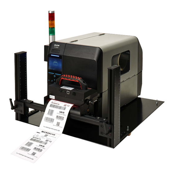
LVS-7500 External System Operations Manual Introduction The LVS-7500 External System offers 100% print quality inspection and barcode verification for Thermal and Thermal Transfer Printers. Features include: • Barcode Validation (Reading of 1D and 2D codes) • Barcode Verification (Grading of 1D and 2D codes to ISO/IEC Standards) •... -
Page 6: Optical Character Recognition (Ocr)
LVS-7500 External System Operations Manual IMPORTANT: The LVS-7500 External System is designed to inspect labels, record and display the results, and supply optional signals to the printer or other external system. The LVS-7500 External System cannot “stop”, “score out void” or “reprint” labels; these are functions that are the responsibility of the printer. -
Page 7: Log In
LVS-7500 External System Operations Manual Log In Follow the steps below to log in to the LVS-7500 External System. 1. Start the LVS-7500 External System software. The Welcome screen appears. Users with the “Automatic Login” feature enabled bypass the screen below and automatically access the screen where they are able to create a new job or load an existing job (as shown in step 3 below). - Page 8 LVS-7500 External System Operations Manual 3. Click the Create a NEW job button to create a new job. Refer to the “Create a New Job” section for complete instructions on creating a new job. Click the Load an EXISTING job button to load an existing job. Refer to the “Load an Existing Job” section for complete instructions on loading an existing job.
-
Page 9: Welcome Screen Overview
LVS-7500 External System Operations Manual Welcome Screen Overview When starting the LVS-7500 External System software, the Welcome screen appears (see below). This screen allows you to log in to the LVS-7500 External System (as described in the previous section) and access the following menu bar functions: •... -
Page 10: Administration
LVS-7500 External System Operations Manual Administration The Administration menu bar feature allows you to choose from the following options. Option Description Data Backup or restore jobs. Calibration Calibrate the LVS-7500 External System. Operators Select operator permissions. Review Audit Trail Review an audit trail of all activity performed on the LVS-7500 External System. - Page 11 For systems that are upgrading from a previous software version to version 5.6.3 or higher: Windows® XP: C:\Program Files\Label Vision Systems\LVS 7500\Jobs Windows® 7: C:\Users\[User Login Name]\AppData\Roaming\Label Vision Systems\LVS 7500\Jobs Data Backup To backup (copy) jobs from the “Jobs” directory to a different folder, drive or network location, follow the steps below.
- Page 12 LVS-7500 External System Operations Manual Data Restore To restore (copy) jobs from a folder, drive or network location to the “Jobs” directory, follow the steps below. 1. Select Administration > Data > Restore from the menu bar. The following screen appears. 2.
- Page 13 The Calibration feature allows you to calibrate the LVS-7500 External System. Calibration is required to keep the LVS-7500 External System in a standard imaging configuration. To calibrate the LVS-7500 External System, you need an Omron Microscan calibration card in perfect condition with all of the calibration information filled out on the card.
- Page 14 LVS-7500 External System Operations Manual 3. Place the white portion on the calibration card in the field of view. The entire image should appear white. Click Continue. The following page appears. Step-by-step calibration instructions are also listed on the right side of the screen. LVS-7500 External System Operations Manual Page 14 of 129...
- Page 15 LVS-7500 External System Operations Manual 4. Place the calibration card under the camera so that as many barcodes are within the field of view as possible. The system displays the ANSII parameters of all the decoded barcodes that the camera detects. LVS-7500 External System Operations Manual Page 15 of 129...
- Page 16 If calibration fails, repeat the calibration process. Be sure to inspect the calibration card carefully for damages and impurities. If the problem still persists, contact Omron Microscan for technical assistance. 7. Click the Save calibration and exit button to save the calibration results and return to the Welcome screen.
- Page 17 LVS-7500 External System Operations Manual Review Calibration History 1. Click Review calibration history. 2. The CSV file viewer page appears (see below), which is time stamped, provides the operator ID, and displays the “before” and “after” calibration image readings. The fields are not user editable in the viewer; they are printable if desired.
- Page 18 LVS-7500 External System Operations Manual Operators The Operators feature allows you to establish operator permissions. 1. Select Administration, and then Operators from the menu bar. 2. The following screen allows you to setup operators and operator permissions. The buttons at the bottom of the screen are described below: Option Description Add new operator...
- Page 19 LVS-7500 External System Operations Manual Option Description Discard changes Click this button to discard any changes made to any operator details. Save changes Click this button to save changes made to any operator details. Done Click this button after all changes are complete. Permissions Operator permissions are described in the table below.
- Page 20 Windows® desktop from the LVS-7500 External System. Accessing the Windows® desktop from the LVS-7500 External System is normally disabled due to CFR-21 part For further information, please contact Omron Microscan about CFR-21 part 11. LVS-7500 External System Operations Manual Page 20 of 129...
-
Page 21: Log On
LVS-7500 External System Operations Manual Log On The Log On menu bar feature allows you to log in or log out of the LVS-7500 External System. About The About menu bar feature allows you to view the LVS-7500 External System software version and contact information. -
Page 22: Create A New Job
LVS-7500 External System Operations Manual Create a New Job Two setup options are available when creating a new job: • Automatic Setup - Utilizing a box drawn around one label, the LVS-7500 External System finds all labels across the roll and automatically draws blemish and barcode sectors with the default setting stored for the corresponding sector types. - Page 23 LVS-7500 External System Operations Manual Manual Setup: LVS-7500 External System Operations Manual Page 23 of 129...
-
Page 24: Automatic Setup
LVS-7500 External System Operations Manual Automatic Setup Follow the steps below to use the Automatic Setup feature. 1. Click the Create a NEW Job button on the Welcome Screen (see below). 2. Select Yes when asked, “Do you want to use the automatic setup feature?” LVS-7500 External System Operations Manual Page 24 of 129... - Page 25 LVS-7500 External System Operations Manual Step 1: Set Label Dimensions 1. Run the roll of labels and stop when reaching the desired label(s). Note that pressing the F12 button on your keyboard allows you to run or freeze images. 2. Click Show more until you can see a complete label with at least a quarter label either above or below the label.
- Page 26 LVS-7500 External System Operations Manual 4. The LVS-7500 External System automatically detects and creates blemish sectors around any other labels across the roll, and also detects and creates sectors around any 1D or 2D barcodes in each label. 5. Enter the name of the job in the Job name field. 6.
-
Page 27: Manual Setup
LVS-7500 External System Operations Manual Manual Setup Follow the steps below to use the Manual Setup feature. Step 1: Set Label Repeat Note: Setting label repeat and synchronization must be performed while the roll is moving. It is recommended that the roll moves slowly so that waste and uninspected material in minimized. The LVS-7500 External System uses an encoder to understand when a label is ready to be inspected. - Page 28 LVS-7500 External System Operations Manual 2. Select No when asked, “Do you want to use the automatic setup feature?” The Step 1: Set label repeat screen appears (see below). 3. In the Desired column, enter the desired value into the inches or millimeter (mm) fields. 4.
- Page 29 LVS-7500 External System Operations Manual Step 2: Synchronize Synchronization Overview Synchronization of the LVS-7500 External System takes the image and electronically creates a repeating pattern for locking. This process emulates the effect generated by a traditional Photo Optic trigger. The principal is simple enough to understand with some pictorial illustrations.
- Page 30 LVS-7500 External System Operations Manual As you can see there are portions of this image attached to the right (after the red line) that look similar. These portions are the where the text goes across the label. The part we are most interested in seeing are the portions that had the black lines going across the image.
- Page 31 LVS-7500 External System Operations Manual When we average just the portions between the lines, we can process and lock in the repeat much faster than doing the entire image. Keeping it as small as possible is the best rule of thumb, though sometimes it may need to be large in order to accomplish the goal.
- Page 32 LVS-7500 External System Operations Manual Synchronization 1. In order to manually synchronize the system, the operator must adjust the two slide bars. The “slice” is a portion of the label that has the best representation of the labels static (unchanging) portion. To change the Width of the “slice”...
- Page 33 LVS-7500 External System Operations Manual Screen Overview Two areas on the screen show an image: The top right image is the full resolution image that has not been altered. The slide bar to the right and below this image will allow the operator to view other parts of the image. Right-click on the full resolution image to zoom in on the image.
- Page 34 LVS-7500 External System Operations Manual Step 3: Create Sectors A sector is defined as an area of interest that is to be analyzed. This step prompts the operator to establish this sector. The software will not process anything located outside the sector. An image must be present to draw a sector.
- Page 35 LVS-7500 External System Operations Manual Copy an Entire Sector 1. Using your mouse, click within the desired sector that is located within a blue box; the sector bounding box then turns red. 2. Right-click inside the desired sector; the sector bounding box turns green. 3.
- Page 36 LVS-7500 External System Operations Manual Multiple sectors can be copied and moved to other labels. This is helpful when an operator has to check the same information on different labels within a repeat. LVS-7500 External System Operations Manual Page 36 of 129...
- Page 37 • Blemish If a sector is deactivated, please contact your Omron Microscan representative to activate the desired sector type. Note: The field located above the sector type list pre-populates with the string that the system is returning for the sector type. For example, if selecting the Barcode read sector type, the field populates with the decoded string.
- Page 38 LVS-7500 External System Operations Manual Direction Box The box labeled Direction is applicable when using the OCR or OCV features; it tells the system the orientation in which to read the characters across the screen. Five types of directions are available: IMPORTANT: The LVS-7500 External System does not distinguish between touching/overlapping characters;...
- Page 39 LVS-7500 External System Operations Manual Sector Types The following is a list of sector types with a description on how to set up a job using that specific sector type. Sector Type 1: Barcode read This sector is used to validate a 1D or 2D barcode label. The LVS-7500 External System inspects the barcode image to determine if it is “readable.”...
- Page 40 LVS-7500 External System Operations Manual Sector Type 2: Barcode grade This sector is used when you want to grade the 1D or 2D barcode image according to ISO/IEC standards. 1. Select Barcode grade. 2. Select the desired direction. 3. Choose an acceptable grade in the Scoring box (see below). 4.
- Page 41 LVS-7500 External System Operations Manual Sector Type 3: OCR Read This sector type is used to “read” the human readable characters located within the drawn sector. IMPORTANT: The LVS-7500 External System does not distinguish between touching/overlapping characters; thus, characters must not touch or overlap. The LVS-7500 External System reads and/or verifies uppercase characters only.
- Page 42 LVS-7500 External System Operations Manual 4. Click the right arrow button. LVS-7500 External System Operations Manual Page 42 of 129...
- Page 43 LVS-7500 External System Operations Manual Create / Learn / Edit Fonts 1. Click the “Create/Learn/Edit” button. The Font Editor page appears. 2. The desired font must be loaded or created. • To load a font from a specific location, click the “Load font from hard disk” button (see “A” in the above screenshot).
- Page 44 LVS-7500 External System Operations Manual 4. Use the buttons at the bottom of the screen to capture the desired image view. Buttons include: Button Description Load image from hard disk Click to load an image stored on a hard disk. Previous Image Click to view the previous image.
- Page 45 LVS-7500 External System Operations Manual Train an Entire Alphanumeric String: • An image comprised of an entire alphanumeric string (0-9 and A-Z) must be present in the training image view. • Use the left click button on your mouse to draw a box around the alphanumeric string in the training image view.
- Page 46 LVS-7500 External System Operations Manual • Click on the desired digit or letter; the gray shade is removed from the selected digit or letter. See example below. In this example, the gray shade is removed after clicking on the “4”. •...
- Page 47 LVS-7500 External System Operations Manual • Use the left click button on your mouse to draw a box around the letter or digit in the training image view (see below). Note that the training image in the screenshot below appears larger after clicking the “Zoom In” button.
- Page 48 LVS-7500 External System Operations Manual • When all changes are complete, click the “Save font to hard disk” button. In the window, save the font to the desired folder (see below). LVS-7500 External System Operations Manual Page 48 of 129...
- Page 49 LVS-7500 External System Operations Manual Sector Type 4: OCV Verify The OCV (Optical Character Verification) sector type is used to score the print quality of the human readable characters within a drawn sector. 1. Select OCV verify. 2. Select the desired direction. 3.
- Page 50 LVS-7500 External System Operations Manual 4. Determine a score (see Scoring Box below for additional information). Scoring Box The OCV Scoring box allows you to choose an acceptable score ranging from 0 to 99. Three scores are available: Score Description Passing The Passing number is a threshold setting.
- Page 51 LVS-7500 External System Operations Manual Sector Type 5: Blemish To use the Blemish sector type, follow the steps below. 1. Select Blemish on the Step 4: Define Sector Type screen; the following screen appears. 2. The software automatically learns the first image it sees after the first sector has been drawn. If the image is not the correct one, or you would like to put a different image into the field of view, click the Relearn button and the software will accept the next image it sees within that sector.
- Page 52 LVS-7500 External System Operations Manual Note: Ctrl+L is a keyboard shortcut for the Relearn button. After pressing Ctrl+L, the system will accept the next image it sees within each Blemish sector and saves the image as the Golden image. This shortcut is available only when the system is in Run mode. After pressing Ctrl+L, a popup message will appear for users without administrative rights.
- Page 53 LVS-7500 External System Operations Manual Field Description This setting changes the size of the Red line that wraps around each label Die cut tolerance when using “fill here” under the Draw section. This area measures the movement of the outside edge of the label compared to the printing within for die movement.
- Page 54 LVS-7500 External System Operations Manual Field Description Clr matrix & die Click this button to clear all matrix and die cut filled sections. Clear all Click this button to Clear all ignored and auto filled sections within a chosen sector. 4.
- Page 55 LVS-7500 External System Operations Manual Preset Configuration Settings The preset configuration settings allow a user to adjust the following six blemish settings on the “Step 4: Define sector type (Blemish settings)” screen: 1. BG<< >>FG sensitivity 2. Foreground sensitivity 3. Background sensitivity 4.
- Page 56 LVS-7500 External System Operations Manual Configure the Preset Settings Follow the steps below to configure the blemish settings for the low, medium and high preset configuration settings. Only users with administrator rights can configure the preset configuration settings. 1. Use the slider bar to adjust the sensitivity or size/tolerance settings for the foreground, background, and die cut settings.
- Page 57 LVS-7500 External System Operations Manual • Click “Low” to apply the blemish settings to the low preset configuration setting. • Click “Med” to apply the blemish settings to the medium preset configuration setting. • Click “High” to apply the blemish settings to the high preset configuration setting. •...
- Page 58 LVS-7500 External System Operations Manual Use the Preset Settings: Users without administrator rights can select the “Low,” “Medium,” and “High” preset buttons to view the image(s) on the “Step 4: Define sector type (Blemish settings)” screen. • Click “Low” to adjust the blemish settings to the “Low” configuration settings as defined by a user with administrator rights.
- Page 59 LVS-7500 External System Operations Manual Step 5: Setup Matching Step 5: Setup Matching is used to set up sequential, matching or incremental information checking. This step does not apply to Blemish modules. Complete the applicable fields and then click the right arrow button. Each field description is listed in the table below.
- Page 60 LVS-7500 External System Operations Manual Description Field options on this page alone. This option will be grayed out when using OCV. Match this text To match a static (unchanging) number, select Match this text and enter the desired string into the text box. Match data in sector If you are using multiple sectors, you may wish to match the data in one sector to the data in another sector.
- Page 61 LVS-7500 External System Operations Manual Description Field Report Label Use this field to enter a report label, such as a name for the sector. The name entered in this field appears on the Summary Report and acts as a unique user-defined identifier of that particular sector.
- Page 62 LVS-7500 External System Operations Manual Global Copy Diagram Labels BEFORE Global Copy • In Label 1 below, sector 3 is matched to sector 1. • In Label 2 below, there are no sectors matched to sector 2. Labels AFTER Global Copy •...
- Page 63 LVS-7500 External System Operations Manual Match to File This feature compares the data decoded within a sector to the data on a file created by the user. Note that the format of the file must be a comma-separated values (CSV) file. Any number of sectors can be set to use “match to file”.
- Page 64 LVS-7500 External System Operations Manual 01111142, 11111110 01111137, 11111110 01111101, 11111110 01111129, 11111110 01111138, 11111110 01111199, 11111110 01111172, 11111110 01111122, 11111110 LVS-7500 External System Operations Manual Page 64 of 129...
- Page 65 LVS-7500 External System Operations Manual Step 6: Alarm Matrix The “Step 6: Alarm Matrix” screen has two different modes, depending on your setting in the LVS7500.ini file. • The “Alarm Matrix: Error Condition View” (Figure 1) is the default configuration and displays error-specific I/O information.
- Page 66 LVS-7500 External System Operations Manual Alarm Matrix: Error Condition View After all sectors have been established, you are prompted to determine an error condition. See the section below entitled “Error Conditions” for more information. Depending on the supplied hardware, the following relay outputs can be triggered by any of the listed error conditions: Line 1 Connected to the Green light, indicating a “good read”.
- Page 67 LVS-7500 External System Operations Manual Column Description States when to activate the “Stop Motion” error condition. You can choose to stop Stop Motion immediately or to not stop at all. Or, you can choose to stop after a certain number of errors occur contiguously (from 1 to 10 errors in a row). Additional options include: Stop Motion Delay This is a set distance that the LVS-7500 External System will output the stop...
- Page 68 LVS-7500 External System Operations Manual Error Code Definitions Error Code Definition Good Read When the system is triggered, the camera takes a picture of the label. The system reads all sectors within the image and compares to the associated sector data in the data file. All sectors match. The system logs to the report the data read from each sector with no error codes attached.
- Page 69 LVS-7500 External System Operations Manual Error Code Definition Not Synced The system has lost synchronization, and is therefore not processing any data outside of looking for a re-sync lock. It will auto log this run portion as “requested to splice” No Read When the system is triggered, the camera takes a picture of the label.
- Page 70 Rewinder/Printer is going faster than what the Camera and PC can handle. LinesperInch or Camera MaxSpeed may be incorrectly set in the ini file. INI settings must only be changed by an Omron Microscan representative. Duplicate Character string has previously been seen in this job.
- Page 71 LVS-7500 External System Operations Manual Alarm Matrix: Pass/Fail View The Alarm Matrix Pass/Fail view displays the pass/fail status of the entire inspection. Click on a setting to cycle through all possible values. Each setting is described in the table below. The Alarm Matrix Pass/Fail view is configured in the LVS7500.ini file >...
- Page 72 LVS-7500 External System Operations Manual Below is a graphical representation of the Alarm Matrix Pass/Fail view settings: Repeat Repeat Repeat Repeat Repeat Repeat Repeat Overall Inspection PASS FAIL PASS PASS PASS FAIL PASS Results for Repeat Number PASS Output FAIL Output Within the Alarm Matrix Pass/Fail view, additional functionality is available when the following settings are enabled in the LVS7500.ini file: UsePassFailMethod=1 5and UseAcknowledgementIO=1.
- Page 73 LVS-7500 External System Operations Manual Setting Description • The roll is moving • The LVS-7500 External System is actively inspecting (that is, the “Start New Run” button has been clicked on the “Operate: Running the Job” screen). PASS Output If the inspection passes, it will output on the specified I/O line for the specified duration.
- Page 74 LVS-7500 External System Operations Manual Step 7: Save Job To Disk 1. Enter a job name in the Job Name field; this saves the current setup. 2. If desired, enter a description or additional job details in the Description field. 3.
- Page 75 LVS-7500 External System Operations Manual LVS-7500 Job Report The LVS-7500 Job Report shows the settings for all created sectors. The LVS-7500 Job Report appears only in Internet Explorer or Firefox web browsers; no other web browser is supported. LVS-7500 External System Operations Manual Page 75 of 129...
- Page 76 LVS-7500 External System Operations Manual Global Copy The Global Copy feature allows you to replicate the setting changes in the same sector across all labels. Global copy works with Automatic or Manual setup. Location of Global Copy button The “Global Copy” button is visible on the following screens: •...
- Page 77 LVS-7500 External System Operations Manual • For all sector types other than Blemish, the Global copy button is visible on the “Step 5: Setup Matching” screen (see below). Global Copy Requirements The Global copy button appears only if: • There is more than one label per repeat. •...
- Page 78 LVS-7500 External System Operations Manual Use Global Copy to Add Sectors to All Labels Across the Screen 1. Create a sector in the left-most lane. 2. Click the Global Copy button. 3. A new sector is created with matching parameters of the first sector. The LVS-7500 External System only creates the number of labels defined in the “Labels per repeat”...
-
Page 79: Load An Existing Job
LVS-7500 External System Operations Manual Load an Existing Job 1. To load an existing job, click Load an Existing Job on the Welcome screen. 2. A list of existing jobs appears. Each column is described in the table below. Column Description Job file List of the job file names. -
Page 80: Operate Screen: Ready To Run
LVS-7500 External System Operations Manual Operate Screen: Ready to Run Each button on the Operate Screen (Ready to Run) is described in the table below. Button Description Delete This Job Click to delete the job. Only operators who are granted the Allow Create NEW Job permission is allowed to delete a job. -
Page 81: Make Ready Mode
LVS-7500 External System Operations Manual Make Ready Mode Clicking the “MakeReady” button allows an operator to: • Simulate how inspections will perform • Simulate how the job created will work in live setting • Test any changes made • Test the system without triggering any output signals that might affect the rewinder/thermal printer After clicking the “MakeReady”... -
Page 82: Operate Screen: Running The Job
LVS-7500 External System Operations Manual Operate Screen: Running the Job The Operate Screen (Running the Job) is typically what you monitor at all times. The features on this screen are described in the table below: Field Description This gives the operator how many rows per second are being analyzed as well as Web Speed how many feet per minute the roll is traveling. - Page 83 LVS-7500 External System Operations Manual Field Description Error Display This is a very helpful feature for the operator to analyze only the errors as they happen. Or, the operator may choose to study one error condition at a time. This feature is activated by clicking on the error.
- Page 84 LVS-7500 External System Operations Manual Show Zoom Window Check the “Show Zoom Window” box to view a magnified image of the label. After checking this box, a blue box appears in the full web image view. Use your mouse to move the blue box over any portion of the label, and then a magnified image appears in the top right corner of the screen.
- Page 85 LVS-7500 External System Operations Manual Bypass Button Click the “Bypass” button to suspend any outputs (such as the stop motion signal) from the LVS-7500. After clicking the button, the screen flashes between yellow and white (see below) and the word “Bypass” scrolls across the top, left corner of the screen indicating the system is in Bypass mode.
- Page 86 LVS-7500 External System Operations Manual • DontProcessDuringBypass=0 indicates the LVS-7500 will process sectors during bypass and will highlight all errors in the Reports\QC File Viewer. Error codes Error codes LVS-7500 External System Operations Manual Page 86 of 129...
- Page 87 LVS-7500 External System Operations Manual • DontProcessDuringBypass=1 indicates the LVS-7500 will not process sectors during bypass and will not check for errors. All bypassed repeats in the Reports/QC File Viewer appear with an !BP error code. Bypassed repeats LVS-7500 External System Operations Manual Page 87 of 129...
-
Page 88: Error Display
LVS-7500 External System Operations Manual Error Display The Error Display log can be accessed on the Operate screen while you are running the job or after you stop the job. Click on an error to view the barcode image and barcode parameters. Barcode parameters Error Display Log... - Page 89 LVS-7500 External System Operations Manual Additional error display options include: Button Description Accept This Error Click this button to approve the error; the error is marked as OK in the error log file and removed from the errors list. The button is active when the job is in run mode. Only operators granted the Allow Accept / Replace Errors permission are allowed to accept the error.
- Page 90 LVS-7500 External System Operations Manual Button Description Replaced Click this button when a label with detected errors is replaced with a known good label. This action marks the label as !RP (replaced) in the error log file and is removed from the errors list. The button is active when the job is in run mode. Only operators granted the Allow Accept / Replace Errors permission are allowed to use this feature.
-
Page 91: Blemish Error Display
LVS-7500 External System Operations Manual Blemish Error Display When viewing a blemish error, three views are available on the screen: • Golden – Displays the golden image • Toggle – Toggles between the golden image and actual image • Actual – Displays the actual blemish image Only a single image of the error is displayed when viewing other types of errors. -
Page 92: Reports / Qc File Viewer
For systems that are upgrading from a previous software version to version 5.6.3 or higher: Windows® XP: C:\Program Files\Label Vision Systems\LVS 7500\Jobs Windows® 7: C:\Users\[User Login Name]\AppData\Roaming\Label Vision Systems\LVS 7500\Jobs The Reports Screen (see below) shows a report for each sector. Each line of data starts with the gate number followed by a date/time stamp, decoded string, error code (if any), and other data associated with the image being inspected. - Page 93 LVS-7500 External System Operations Manual Sample Reports Errors Only Report LVS-7500 External System Operations Manual Page 93 of 129...
- Page 94 LVS-7500 External System Operations Manual Run Log LVS-7500 External System Operations Manual Page 94 of 129...
- Page 95 LVS-7500 External System Operations Manual 1D Grade Details View 1D grade details by double-clicking on a job in the 1D grading column. LVS-7500 External System Operations Manual Page 95 of 129...
- Page 96 LVS-7500 External System Operations Manual Run Log with Images Blemish, barcode, and OCR/OCV error images can be viewed by clicking on the red blemish cell in the log file. An error display screen will then pop-up. If the error is a blemish, the Golden Image will show on the Left; a Toggle between Golden and Actual in the center;...
- Page 97 LVS-7500 External System Operations Manual Summary Report The LVS-7500 Summary Report can be accessed by clicking on the Summary Report button when viewing a log file. The report gives a summation of the entire job and each sector’s settings and parameters. It also shows example images where sectors were drawn.
-
Page 98: Preventive Maintenance
Replace the Calibrated Conformance Standard Test Card every two years. If you have any questions or concerns about the performance of the LVS-7500 External System, please call your local Omron Microscan distributor or Omron Microscan technical support: +1-800-762-1149 | +1-425-203-4841 | helpdesk@microscan.com... -
Page 99: Troubleshooting
LVS-7500 External System Operations Manual Troubleshooting Problem Description Possible Causes • The roll of labels is not moving. System will not acquire images • Encoder is not in contact with moving roll of labels. • Encoder cable is not plugged in or is damaged. •... -
Page 100: Mechanical Diagrams
LVS-7500 External System Operations Manual Mechanical Diagrams All technical drawings are copyrighted in respect to their manufacture. All respected trademark rights are reserved. LVS-7500 Basic Wire Diagram LVS-7500 External System Operations Manual Page 100 of 129... -
Page 101: Lvs-7500 Stop Motion And Light Tower Printer Interface
LVS-7500 External System Operations Manual LVS-7500 Stop Motion and Light Tower Printer Interface The purpose of the Alarm Matrix is to effectively connect to the Stop-Motion/Light Tower Unit. Line 1 (D0) is hard wired to the GREEN Light. All sections listed under the Trigger Column that show “Line 1” will turn on the GREEN light on the light tower. - Page 102 LVS-7500 External System Operations Manual Line 5 (D3) – The Audible Alarm, located inside the Stop Motion/Light Tower Unit, is programmed to follow the RED light (Line 3). When the audible alarm is not required, the operator will have to change the INI settings. There is no access to Line 5 through the Alarm Matrix.
-
Page 103: Appendix A: Lvs7500.Ini File
• For new installations of software version 5.6.3 on Windows® 7 Professional and Windows® 8.1 Professional operating systems: C:\LvsData\LVS 7500 • For systems that are upgrading from a previous software version to version 5.6.3 or higher: Windows®... - Page 104 MaxThumbnailsPerSector limits how many thumbnails are used for a single sector’s errors. • ScrollMax controls the maximum size of a blemish. Value is in inches. ShowDieCutCrossHatch is used by Omron Microscan technicians. Default is 0 • • ShowMatrixDieCutControls is used to make the sensitivity controls for Matrix and Die Cut available during setup.
- Page 105 TargetDPI is used for Blemish quality. Lower settings help the system to run faster but fewer errors are found. Higher settings slow the system but more errors will be found. It is advised to leave this setting as is unless instructed by an Omron Microscan representative. •...
- Page 106 Numeric=0123456789 AlphaNumeric=ABCDEFGHIJKLMNOPQRSTUVWXYZ0123456789 NumericAlpha=0123456789ABCDEFGHIJKLMNOPQRSTUVWXYZ Debug: Debug is not user configurable and should not be altered unless requested by an Omron Microscan representative. [Debug] Mode=0 Encoder Parameters: The Encoder parameters are used as instructions sent to the External Control Unit of the LVS-7500.
- Page 107 Then, the LVS-7500 re-inspects the label after it moves back under the camera and continues logging from that point. The StopMotionDelay is the minimum allowed distance that Omron Microscan has determined that the Stop • Motion Output signal can be sent without missing any outputs. This should not be changed unless instructed by an Omron Microscan representative.
- Page 108 [Jobs] Path=.\Jobs Lumenera: The Lumenera settings are used for Lumenera specific area scan camera’s and should not be altered unless requested by an Omron Microscan representative. • Exposure is the exposure setting of a Lumenera USB camera. • FixedSpeed is the speed of an external belt or conveyor in feet per minute.
- Page 109 When this feature is turned on, narrow characters (such as the letter I or the digit 1) may appear stretched when displayed. This value should only be changed after consulting an Omron Microscan technical support representative.
- Page 110 These settings affect the ability of the LVS-7500 to process cartons on a conveyor that may not be perfectly in line. • CloseEnoughAngle and TrackImages are parameters used by [Blemish] and should only be changed by an Omron Microscan technician. [SkewBlemish] CloseEnoughAngle=0.05...
- Page 111 The Sync Parameters are used for setting the system to be able to lock onto the customers’ labels. • HopX and HopY tracks the movement of the labels in the horizontal and vertical direction. Log is to be used by an Omron Microscan technician only. • [Sync] HopX=0.0625...
- Page 112 • CameraSpeedWarning tells the software when to show a warning message if the camera gets to the specified speed. ChangeRollOnFly is used only if directed by an Omron Microscan technician. • • ClearPrompts - If set to zero (default), the system will re-use the most recently entered data for prompts. If set to non-zero, the computer will start with blanks and the operator must fill in all data.
- Page 113 HideAlarmMatrix=0 (default) displays the Alarm Matrix screen. HideAlarmMatrix=1 hides the Alarm Matrix screen. The software will skip “Step 6: Alarm Matrix” and the user will never see this screen. IgnoreHealthCheck is for Omron Microscan technician use only. • • Inactivity Timeout automatically logs out any user if the system is left idle for the defined amount of time.
- Page 114 This allows the system to recover instead of generating non-stop mismatch errors after an inserted or deleted label. ShowBlemishMotion should only be changed by an Omron Microscan technician. •...
- Page 115 LVS-7500 External System Operations Manual • TurretSignalDelay sets delay (in inches) from the moment the turret signal is received, until the Change Roll on the fly command is activated. • UseBypassSignal turns on the monitoring of the Bypass signal Input line. Activated on LOW signal. •...
- Page 116 Host, Port1, Port2, etc.) do not apply if the LVS-7500 is not connecting to another system. • Host: Do not change this setting; leave as is. Port1: Enter the port where the first external system will be listening for Omron Microscan data. • •...
-
Page 117: Appendix B: Epedigree
LVS-7500 External System Operations Manual Appendix B: ePedigree Systems with ePedigree enabled are using the normal LVS-7500 software with enhanced tracking features. Below are a couple of steps that highlight the LVS-7500 ePedigree process. 1. When drawing a sector over a 2D Data Matrix code, make sure that the center of the X within the sector is close to the center of the 2D code. - Page 118 LVS-7500 External System Operations Manual 2. Choose the Check for Duplicates option to make sure that the barcode’s encoded data is unique for this job or the sect. When running the job, a !DU error will show up if the software finds a duplicate of the barcode. LVS-7500 External System Operations Manual Page 118 of 129...
- Page 119 LVS-7500 External System Operations Manual 3. Draw an OCR sector around the human readable characters and let it match its corresponding barcode. In this example, we have to start matching OCR at position 17 of the barcode, because the barcode is 28 characters long and the human readable characters match the last 12 characters of the barcode.
-
Page 120: Appendix C: Imagesaver Instructions
For systems that are upgrading from a previous software version to version 5.6.3 or higher: Windows® XP: C:\Program Files\Label Vision Systems\LVS 7500 Windows® 7: C:\Users\[User Login Name]\ AppData\Roaming\Label Vision Systems\LVS 7500 2. Create and name a target folder where images can be saved (see below). - Page 121 LVS-7500 External System Operations Manual 4. Save changes and close the Lvs7500.ini file. 5. Open the LVS-7500 program. 6. Click OK at the Image Saver warning (see below). 7. Click the Create a New Job button and stay at the Label Repeat screen. 8.
-
Page 122: Saving Images With A Label Repeat
For systems that are upgrading from a previous software version to version 5.6.3 or higher: Windows® XP: C:\Program Files\Label Vision Systems\LVS 7500 Windows® 7: C:\Users\[User Login Name]\ AppData\Roaming\Label Vision Systems\LVS 7500 5. Create and name a target folder where images can be saved (see below). - Page 123 LVS-7500 External System Operations Manual 7. Save changes and close the Lvs7500.ini file. 8. Open the LVS-7500 program. 9. Click OK at the Image Saver warning (see below). 10. Click the Load an Existing Job button and choose the job that was created for image capturing. 11.
-
Page 124: Appendix D: Upgrading Software
LVS-7500 External System Operations Manual Appendix D: Upgrading Software 1. After receiving the LVS-7500 software files to download, open the .zip folder and double-click the Setup.exe icon (see below). 2. When the InstallShield Wizard appears, click Next (see below). LVS-7500 External System Operations Manual Page 124 of 129... - Page 125 LVS-7500 External System Operations Manual 3. Click Install to begin installation (see below). 4. After clicking the Install button, the InstallShield Wizard begins installation and shows a status bar (see below). LVS-7500 External System Operations Manual Page 125 of 129...
- Page 126 LVS7500.ini file locations: • For new installations of software version 5.6.3 on Windows® 7 Professional and Windows® 8.1 Professional operating systems: C:\LvsData\LVS 7500\Lvs7500.ini. • For systems that are upgrading from a previous software version to version 5.6.3 or higher: Windows® XP: C:\Program Files\Label Vision Systems\LVS7500\LVS7500.ini Windows®...
- Page 127 Values in the LVS7500.ini file can be changed, but do not delete any extra line items in the file. 9. When all values are the same, close the “Original LVS7500.ini” file. 10. Perform a “Save As” to “LVS7500.ini” file and save the file to the LVS 7500 folder (see below). LVS-7500 External System Operations Manual...
-
Page 128: Appendix E: Automatic Login
LVS-7500 External System Operations Manual Appendix E: Automatic Login The Automatic Login feature allows a user to automatically log in to the LVS-7500 External System software without entering an Operator ID and Password. The settings for Automatic Login are controlled in the LVS7500.ini file > [System] section > AutoLogin setting. •... - Page 129 LVS-7500 External System Operations Manual To setup an operator to allow Automatic Login, follow the steps below. 1. Click “Administration” and then “Operators” from the menu bar. 2. On the “Operator Administration” screen, click the “Add new operator” button. 3. Enter the operator name in the “Operator ID (short name)” field and “Operator name (full)” field. The Operator name must match the Windows user name.
Need help?
Do you have a question about the LVS 7500 and is the answer not in the manual?
Questions and answers