Table of Contents
Advertisement
Table of Contents
Overview ................................................................................................................................................................ 2
Important Safety Instructions ............................................................................................................................. 2
The imVision System ............................................................................................................................................. 3
iPatch Panel ....................................................................................................................................................... 3
imVision Controller ............................................................................................................................................. 3
Ordering Panels in the imVision System ............................................................................................................... 4
Following Prompts in the imVision System ........................................................................................................ 5
Screen Lock PIN Feature .................................................................................................................................. 5
Audible and Visible Feedback ........................................................................................................................... 6
imVision System Manager Software .................................................................................................................. 6
Settings .................................................................................................................................................................. 7
Patching Mode ................................................................................................................................................... 7
Patching and Tracing ............................................................................................................................................. 7
Performing Guided Patching Jobs ..................................................................................................................... 7
Performing Unguided Patching Jobs ................................................................................................................. 8
Tracing a Patch Connection .............................................................................................................................. 8
Correcting Patching Errors ................................................................................................................................ 8
Confirming a Patch Connection........................................................................................................................... 10
Connecting Controllers in a Zone ........................................................................................................................ 11
Troubleshooting ................................................................................................................................................... 13
© 2016 CommScope, Inc.
All rights reserved
SYSTIMAX
®
imVision
User Guide
®
Controller
This product is covered by one or more U.S.
patents or their foreign equivalents. For patents, see
www.commscope.com/ProductPatent/ProductPatent.aspx
860547876
August 2016
Issue 3
Page 1 of 15
Advertisement
Table of Contents

Related Manuals for CommScope SYSTIMAX imVision


Summary of Contents for CommScope SYSTIMAX imVision
-
Page 1: Table Of Contents
Confirming a Patch Connection........................... 10 Connecting Controllers in a Zone ........................11 Troubleshooting ..............................13 This product is covered by one or more U.S. © 2016 CommScope, Inc. patents or their foreign equivalents. For patents, see Page 1 of 15 All rights reserved... -
Page 2: Overview
Follow all warnings and instructions marked on this product. ® This product should be operated using only the power supply provided by CommScope with the product. Consideration should be given to the connection of the equipment to the supply circuit and the effect that overloading of the circuits might have on overcurrent protection and supply wiring. -
Page 3: The Imvision System
User Guide 860547876 August 2016 ® The imVision System The imVision System is comprised of three main components: iPatch Panels, either iPatch copper panels or iPatch fiber shelves imVision Controller (with touchscreen display) imVision System Manager software Note: The imVision System supports the previous generation Panel Manager and Rack Manager Plus. -
Page 4: Ordering Panels In The Imvision System
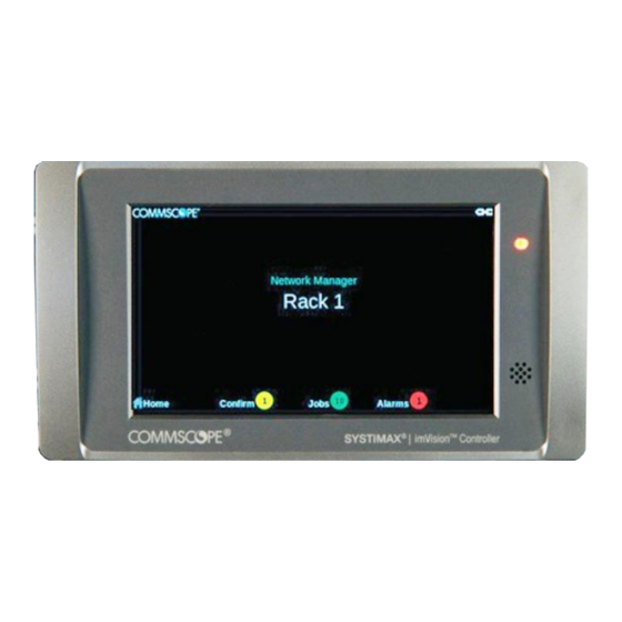
860547876 www.commscope.com ® imVision Controller User Guide “Ready” Screen After a period of inactivity, the display screen will turn off. The imVision Controller LED will light up when attention is required, such as pending Jobs, Alarms or Confirmations. Tap to activate the display and touch the colored circles next to Confirm, Jobs, or Alarms. -
Page 5: Following Prompts In The Imvision System
User Guide 860547876 August 2016 Following Prompts in the imVision System The imVision System provides helpful feedback on its controller display. While performing work on panels or responding to alarms, be sure to follow any prompts that appear on the display. -
Page 6: Audible And Visible Feedback
860547876 www.commscope.com ® imVision Controller User Guide imVision Controller users can also change screen lock PIN settings on the Controller web UI, as shown below. Audible and Visible Feedback To help technicians work efficiently and accurately, the imVision System provides feedback to the user in a number of ways –... -
Page 7: Settings
User Guide 860547876 August 2016 imVision System Manager software also alerts the administrator to conditions such as unauthorized changes to the physical infrastructure, or work that was not performed as scheduled. Please note that imVision Controller requires imVision System Manager software version 7.0 or... -
Page 8: Performing Unguided Patching Jobs
860547876 www.commscope.com ® imVision Controller User Guide In addition to the display information, LEDs above the relevant ports will indicate where to add or remove the connection for the given job. Completing each patching job automatically queues the next job on the list to be performed. - Page 9 User Guide 860547876 August 2016 Step 2 – Use the Change button to break existing connection relationships To break existing connection relationships for a traced port, press the Change button on the imVision Controller’s display. After pressing the Change button, select Yes to continue past a warning about the connection being broken.
-
Page 10: Confirming A Patch Connection
860547876 www.commscope.com ® imVision Controller User Guide Confirming a Patch Connection If the imVision System no longer knows both ends of a connection, a Confirm tab will appear on the display. To confirm a connection, tap the Confirm tab on the display. You will see a list of any patch connections that need to be confirmed. -
Page 11: Connecting Controllers In A Zone
User Guide 860547876 August 2016 If you need to… You should… Locate the unknown end of the patch cord. Then press and hold the unknown port’s Confirm the other end of a connection button for 2 seconds. between two iPatch panel ports. - Page 12 860547876 www.commscope.com ® imVision Controller User Guide Configure a Zone Containing Three imVision Controllers Controller The “Controller” communications mode should be selected if the port is used to connect from the imVision Controller to another controller in the zone.
-
Page 13: Troubleshooting
Manager to mark the port broken”. See the imVision System d. Port’s button has failed. Manager help topic “Marking Ports and Outlets as Broken” or contact CommScope support. e. Verify HD Fiber module is properly seated in the shelf backplane. - Page 14 Controller display does not change. imVision Controllers Are Connected Incorrectly. b. Panel’s or module’s sensor is bad. b. Contact CommScope Support via the Support Portal. You attempt to add a patch a. The port configuration switches on one or more a.
- Page 15 “delete” button. This will tell all of the remaining racks in the patching zone that the controller in question has been removed. e. Contact CommScope Support via the Support Portal. e. The Controller in question has failed A “Panel X not communicating a.
Need help?
Do you have a question about the SYSTIMAX imVision and is the answer not in the manual?
Questions and answers