Advertisement
Quick Links
NEBMS1G9/W9E...Q5LE6
Motor cable
Assembly instructions
8135054
2020-04b
[8135056]
Translation of the original instructions
© 2020 all rights reserved to Festo SE & Co. KG
1
Applicable documents
All available documents for the product è www.festo.com/sp.
2
Safety
2.1
Safety Instructions
–
Do not connect or disconnect plug connector when powered.
–
Only mount the product on components that are in a condition to be safely
operated.
–
Assembly and installation should only be carried out by qualified personnel.
These personnel have electrical training or a relevant qualification.
2.2
Intended use
Connection of a stepper motor EMMS-ST-42/57 to a motor controller CMMT-
ST/CMMS-ST/CMMO-ST.
3
Configuration
3.1
Product design
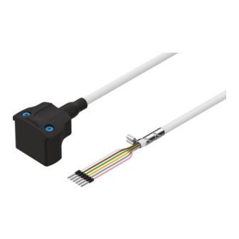
Fig. 1 NEBM-S1G9-E-...-Q5-LE6
Fig. 2 NEBM-S1W9-E-...-Q5-LE6
3.2
Contact assignment
Electrical connection 1
Assignment/signal
Field device side
1 Socket
Pin
1
String A
2
String A/
3
String B
4
String B/
5
–
6
–
7
Brake + 24 V
8
Brake GND
9
–
1) Colour code in accordance with IEC 60757:1983-01
Tab. 1 Contact assignment
Festo SE & Co. KG
Ruiter Straße 82
73734 Esslingen
Germany
+49 711 347-0
www.festo.com
8135054
1 Sub-D socket, 9-pin
2 Wire end sleeves 8 mm (6x)
3 Cable
4 Screened connection
1 Sub-D socket, 9-pin
2 Wire end sleeve 8 mm (6x)
3 Cable
4 Screened connection
Electrical connection 2
Controller side
2 Wire ends
1)
WH
BN
GN
YE
–
–
GY
PK
–
4
Assembly
4.1
Mounting of electrical connection 1
1. Align socket 1 to fit the plug.
2. Connect socket 1 to the plug.
4.2
Wiring
Character
Cable characteristic
istic
-E-
Suitable for energy chains
Tab. 2 Wiring
4.3
Mounting in energy chain
1. Lay the chain out lengthwise.
2. Place the cables on the chain, making sure they are not twisted.
3. Separate cables from each other using separators/drilled holes.
4. Do not connect cables together.
Fig. 3
5. Maintain space X. X > 10% of the cable diameter D.
If the chain is suspended vertically: increase space X.
Fig. 4
6. Align chain in the operating position:
–
Make sure that the radius is greater than the bending radius R of the
cables.
–
Cables can move freely in the bending radius KR of the energy chain.
Ä Cables are not forced through the chain.
7. Mount the energy chain è corresponding instructions.
8. Fasten cables:
–
with short energy chains (length < 1 m) at both ends of the chain
–
with long sliding energy chains (length > 1 m) only at the driver end
Fig. 5
9. Do not move cables all the way to the fastening point.
Ä Mounting space A between the fastening point and bending movement is
maintained.
NOTICE!
Damage to cables if the chain breaks.
•
Replace cables after a chain break.
NOTICE!
Malfunction and material damage due to vertically suspended cables.
The cables stretch.
•
Regularly check the length of the cables.
•
Readjust the cables if required.
Wiring
In energy chain or flexible
Advertisement

Related Manuals for Festo NEBMS1G9-E-Q5-LE6 Series


Summary of Contents for Festo NEBMS1G9-E-Q5-LE6 Series
- Page 1 4. Do not connect cables together. 2020-04b [8135056] 8135054 Translation of the original instructions © 2020 all rights reserved to Festo SE & Co. KG Applicable documents Fig. 3 5. Maintain space X. X > 10% of the cable diameter D. If the chain is suspended vertically: increase space X.
- Page 2 Technical data NEBMS1G9/W9E...Q5SE6 Cable characteristic Suitable for energy chains Cable composition [mm²] 6x0.34 Shielding Shielded Cable diameter [mm] 6.2 ± 0.2 Mounting space [mm] Current rating at 25 °C Note on current rating at >25 °C Reduction of the current rating by 1%/K Operating voltage range 0 … 72 Bending radius...