Advertisement
Quick Links
Advertisement

Related Manuals for Datcon DT1010 Series

Summary of Contents for Datcon DT1010 Series
- Page 1 DT1010 xx xx Temperature / Resistance / Potentiometer Transmitter Operating Instructions...
- Page 2 DT1010 xx xx Contents 1. About this document .............4 1.1. Function ................... 4 1.2. Target group................4 1.3. Symbolism used............... 4 2. For your safety ...............5 2.1. Authorized personnel ............... 5 2.2. Appropriate use................ 5 2.3. Warning about misuse ............. 5 2.4.
- Page 3 DT1010 xx xx 7. Setting-up ..............17 7.1. First steps................17 7.2. Connecting wire setting............18 7.3. Input mode setting..............19 7.4. Analogue output setting ............20 7.5. Error current / voltage setting..........20 7.6. Setting averaging ..............21 7.7. Output refresh time setting............. 23 7.8.
- Page 4 DT1010 xx xx 1. About this document 1.1. Function This operating instructions manual has all the information you need for quick set-up and safe operation of DT1010 xx xx. Please read this manual before you start setup. 1.2. Target group This operating instructions manual is directed to trained personnel.
- Page 5 For safety and warranty reasons, any internal work on the instruments must be carried out only by DATCON personnel. 2.2. Appropriate use The DT1010 xx xx is a Temperature / Resistance / Potentiometer Transmitter.
- Page 6 DT1010 xx xx 3. Product description 3.1. Delivery configuration The scope of delivery encompasses: Delivered items • DT1010 xx xx • documentation: this operating instructions certification warranty 3.2. Type designation 20180403-V1...
- Page 7 DT1010 xx xx 3.3. Principle of operation The DT1010 xx xx Temperature / Resistance / Area of application Potentiometer Transmitter provide signal transmission and conversion between sensor or resistance / potentiometer and signal processing unit. The transmitter feature complete 3-way isolation: the input to output and both to the power supply circuits are isolated.
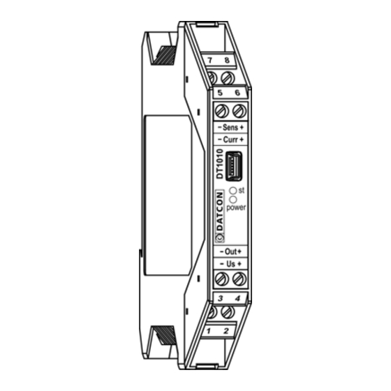
- Page 8 DT1010 xx xx 3.5. Indicators, USB connector The following figure shows the indicators and the USB connector on the instruments front: 1. The „power” green indicator has two function: - continuous light indicates that the instrument is in measuring mode - a short flash indicates that a successful communication has granted with the configuration software.
- Page 9 DT1010 xx xx 3.6. Storage and transport This instrument should be stored and transport in places whose climatic conditions are in accordance with chapter 10.1. Technical specifications, as described under the title: Environmental conditions. The packaging of DT1010 xx xx consist of environment- friendly, recyclable cardboard is used to protect the instrument against the impacts of normal stresses occurring during transportation.
- Page 10 DT1010 xx xx 4. Mounting 4.1. General instructions The instrument should be installed in a cabinet with sufficient IP protection, where the operating conditions are in accordance with chapter 10.1. Technical specification, as described under the title: Operating conditions. The instruments are designed in a housing for mounting on Mounting position TS-35 rail.
- Page 11 DT1010 xx xx 4.3. Mounting The following figure shows the mounting procedures (fixing on the rail): Mounting on the rail The mounting doesn’t need any tool. 1. Tilt the instrument according to the figure; put the instrument’s mounting hole onto the upper edge of the rail (figure step 1.).
- Page 12 DT1010 xx xx 5. Connecting 5.1. Preparing the connection Always observe the following safety instructions: • The connection must be carried out by trained and authorized personnel only! • Connect only in the complete absence of supply voltage • Use only a screwdriver with appropriate head Take note the suitability of the connecting cable Select and prepare (wire cross-section, insulation, etc.).
- Page 13 DT1010 xx xx 5.2. Connecting sensor / resistor / potentiometer to the input The following figure shows the wiring plan, connecting the sensor / resistor / potentiometer to the input: Wiring plan, connecting the sensor / resistor / potentiometer to the input (see also “Application example”)
- Page 14 DT1010 xx xx 5.3. Connecting the signal processing unit and the power supply The following figure shows the wiring plan, connecting the signal processing unit and the power supply: Wiring plan, connecting the signal processing unit and the power supply (see also “Application example”) Be careful the polarity of...
- Page 15 DT1010 xx xx 6. The first start-up, indicators 6.1. The first start-up After connecting the DT1010 xx xx is ready to work with the factory default parameters. When you are going to use other parameters you should set-up the instrument according to Chapter 7. Factory default settings: •...
- Page 16 DT1010 xx xx 6.2. Indicators (1) power (green): mode an communication indicator (2) st. (red): mode and error indicator The two indicator gives information in conjunction as follows: • Measurement mode: power: light, st.: dark. • Error state: power: light, st.: blinking. The number of blinkings gives the error information while the output current is forced into 3.2 mA or 20.8 mA (depends on setting).
- Page 17 DT1010 xx xx 7. Setting-up 7.1. First steps For setting-up you need: Necessary tools • mini USB B (5 pin)-USB A cable • USB driver install program • DT1010_DT1310 v2013-09-18 - 2015-03-25.exe configuration software • You have to install once the virtual COM driver before use Install the virtual COM the configuration program first.
- Page 18 DT1010 xx xx 7.2. Connecting wire setting The sensor / resistance / potentiometer can be connected to Function the input either with 4 / 3 / 2 wire. The 4 wire connection gives the best result: the instrument is able to compensate the connecting cable resistances. The 3 wire mode is a compromise it may give a good result when all the 3 wire have same resistance.
- Page 19 DT1010 xx xx 7.3. Input mode setting The instrument has four measuring modes: Function • temperature • potentiometer % • potentiometer scaled • resistance [Factory default: temperature measurement.] 1. Select the appropriate input mode by clicking the button. Sequence of operations The figure shows the factory default setting.
- Page 20 DT1010 xx xx 7.4. Analogue output setting The output signal can be current: 0 / 4-20 mA, or Function voltage 0 / 2-10 V. (should be specified at order) [Factory default: 4-20 mA] 1. Select the appropriate output signal by clicking the Sequence of operations button.
- Page 21 DT1010 xx xx 7.6. Setting averaging The instrument performs cca. 12 measurements in each Function seconds. (In 3 wire mode only 5 measurements). The measurement result is generated as the average of several measurements. Here you can define the number of measurements that should be used for calculating the averaged numerical value.
- Page 22 DT1010 xx xx Settling time after stabilizing the input signal (3 wire mode): Averaging number: Settling time (sec): 0.25 13.6 20180403-V1...
- Page 23 DT1010 xx xx 7.7. Output refresh time setting The output current / voltage refresh time can be set Function independently from the measuring time. There are 6 different refresh times (sec): 0.1; 0.3; 0.5; 1.0; 1.5; 2.0 1. Select the appropriate output signal by clicking the Sequence of operations button.
- Page 24 DT1010 xx xx 7.8. Analogue output scaling There are two output versions of the instrument: Function DT1010 xx Ix xx: 0 / 4-20 mA current output or DT1010 xx U xx: 0 / 2-10 V voltage output It can be assign any temperature or resistance range or potentiometer scale to the output.
- Page 25 DT1010 xx xx 7.9. Two wire zeroing When the sensor / resistance / potentiometer is connected Function to the input with two wire, the wire resistance will cause a measurement error. With this function can be compensated this error. (The compensation will work only properly at the same ambient temperature.) [Factory default: wire resistance = 0 Ohm.] This setting will work only when the two wire mode is...
- Page 26 DT1010 xx xx 7.10. Sensor correction values The real sensor characteristics may differ from the Function theoretical R-°C curve. The difference will cause a measurement error on temperature measurement. When you are capable to calibrate the sensor on minimum 3 points you will know the resistance difference of the theoretical and real characteristics.
- Page 27 DT1010 xx xx The figure shows the factory default settings. Sequence of operations 2. Type-in the 3 temperature value: 3. Type-in the bold resistance difference values: The setting is ready. 20180403-V1...
- Page 28 DT1010 xx xx 7.11. Potentiometer calibrating Before selecting potentiometer measuring mode it should Function be calibrated the potentiometer. At calibrating must define the start and the end position of potentiometer’s wiper. So you can fit the measuring range of the instrument to the potentiometer scale.
- Page 29 DT1010 xx xx 3. Set the potentiometer wiper to the end position, than click on the right button. You will see on the right button the resistance value of the potentiometer in the end position. Note: Any wiper position can be assign to the 0% and 100% so you can realize reverse operation too.
- Page 30 DT1010 xx xx 7.12. Potentiometer scaling When you are going to use the potentiometer with better Function resolution than 1% you can assign resistance values with 1, 2, 3, 4 decimal resolution to the start and end position of the potentiometer.
- Page 31 DT1010 xx xx 7.13. New password setting Here you can exchange the factory password for a new Function one. The range is: 0-9999. [Factory default: 1000] 1. Type-in the new password into the upper field. (0-9999) Sequence of operations 2. Type-in one more time the new password into the lower field.
- Page 32 DT1010 xx xx 7.14. Resetting default settings In this case all the settings are deleted, and the default Function settings are restored. Using this function makes sense in that case, when the settings of the instrument have changed so much, that it is easier to start the setting-up process from the default factory setting.
- Page 33 DT1010 xx xx 7.15. Analogue output limiting The analogue output works correspond with NAMUR Function standard. For example the 4–20 mA type output has 3,8 mA – 20,5 mA current range. You can limit this range. For example: let the low output limit is 12 mA and the high output limit is 17 mA.
- Page 34 8.2. Repairing There is no user repairable part inside the instrument. In accordance with Point 2.1.: For safety and warranty reasons, any internal work on the instrument must be carried out by DATCON personnel. 20180403-V1...
- Page 35 DT1010 xx xx 9. Dismounting 9.1. Dismounting procedure The following figure shows the dismounting procedures: Dismounting from the rail The dismounting procedure needs a screwdriver for slotted screws. 1. Before dismounting disconnect all wires. 2. Put the screwdriver end into the fixing assembly’s hole (figure step 1.).
- Page 36 DT1010 xx xx 10. Appendix 10.1. Technical specification Input parameters Input signal: Pt100 / Pt500 / Pt1000 / Cu50 / Ni100 / Ni1000 sensor or resistance / potentiometer Connection: 4 / 3 / 2 wire Measuring current: 880 μA (Pt1000: 250 μA) Sensor dissipation 80 μW (sensor temp.: 0 ºC) 270 μW (sensor temp.: 800 ºC)
- Page 37 DT1010 xx xx Galvanic isolation Test voltage: 2500 VDC (between input-output, input- power supply terminals) 500 VDC (between output-power supply terminals) Power supply Power supply: 19-35 VDC Power consumption: 1.6 W Ambient conditions: Operating temperature range: 0-60 °C -20 - +60 °C on customer request Storage temperature range: -20 - +70 °C Relative humidity:...
- Page 38 DT1010 xx xx 10.2. Application example 20180403-V1...
- Page 39 DT1010 xx xx 20180403-V1...
Need help?
Do you have a question about the DT1010 Series and is the answer not in the manual?
Questions and answers