Advertisement
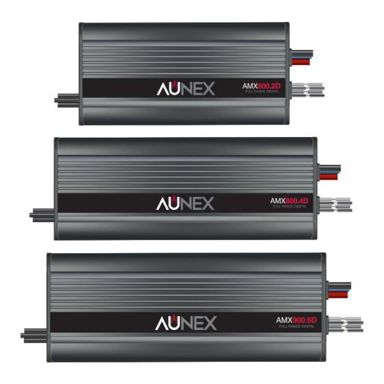
AMX900.6D
FULL RANGE DIGITAL
AMX Series Amplifiers
Mini IPX Class D Digital Amplifier Series
Models: AMX600.2D, AMX800.4D, AMX900.6D
Installation and Operation Manual
Please take time to thoroughly read through this manual to familiarize yourself with your new amplifier.
This will ensure that your amplifier will perform at its optimum capabilities.
Para obtener una copia de este manual en español, visite
www.aunexusa.com
y luego vaya a la página
del producto que necesita. Haga clic en la pestaña Soporte y descargue su manual en español.
Advertisement
Table of Contents

Related Manuals for Aunex AMX Series


Summary of Contents for Aunex AMX Series
- Page 1 AMX900.6D FULL RANGE DIGITAL AMX Series Amplifiers Mini IPX Class D Digital Amplifier Series Models: AMX600.2D, AMX800.4D, AMX900.6D Installation and Operation Manual Please take time to thoroughly read through this manual to familiarize yourself with your new amplifier. This will ensure that your amplifier will perform at its optimum capabilities.
- Page 2 Congratulations and thank you for purchasing an Aunex AMX Series Amplifier. This product has been engineered and manufactured utilizing precision quality parts and craftsmanship. Improvements in sound quality and system performance will be greatly enhanced with the use of this amplifier.
- Page 3 General Feature Set of the AMX Series Amplifiers • Heavy Density Aluminum Extruded Heatsink • IPX67 Element Ready • Die Cast End Cap with Tone Control Access Panel • 4 Layer PCB, SMD Technology • Conformal Coated PCB • Differential Balanced RCA Inputs •...
-
Page 4: Important Safety Considerations
What’s Included • (1) AMX Series Mini Amplifier • (1) In-Line Fuse Holder with Mini ANL Fuse o AMX600.2D is supplied with a 60A Fuse o AMX800.4D is supplied with a 80A Fuse o AMX900.6D is supplied with a 100A Fuse •... - Page 5 In addition, each AMX Series amplifier has a Tone Control Access panel which will prevent water from entering the amplifier circuit board. However prolonged exposure to extreme water and high...
-
Page 6: Mounting Placement
For optimum sound quality, it is highly recommended that you purchase Aunex wiring accessories as they are designed to give your amplifiers high-quality signal it needs to operate at peak performance levels. - Page 7 Side Panel Layout Continued AMX600.2D X-Over Filter Filter Freq. Boost Eq. Input Gain Clip Preouts Full Inputs Input 40Hz 400Hz 18dB AMX600.2D Speaker Outputs Bridge Ch.1 Ch.2 +12V Remote Ground AMX800.4D Ch.3 & Ch.4 Ch.1 & Ch.2 X-Over Filter X-Over Filter Filter Freq.
- Page 8 Side Panel Layout Continued AMX900.6D Ch.1 & Ch.2 Ch.3 & Ch.4 X-Over Filter X-Over Filter Input Gain Filter Freq. Filter Freq. Input Gain Full Full Input Inputs 40Hz 400Hz 40Hz 400Hz Clip Clip Full Input Mode Clip 40Hz 400Hz Input Gain X-Over Filter Filter Freq.
- Page 9 Side Panel Layout Continued 1. Input Gain: Use these Input Gain Potentiometers to match the output voltage of your headunit / source unit to the input circuit of your amplifier. These Input Gains are not a volume knob. A simple method of setting your Input Gains is to turn your headunit / source unit up to approximately ¾...
- Page 10 8. Low Level RCA Inputs: These are your differential balanced inputs that are used to connect audio signal from your headunit / source unit to your amplifier. Your AMX Series Amplifier is capable to receiving either High Level Speaker Outputs or Low-Level RCA cables.
- Page 11 Side Panel Layout Continued 9. Speaker Outputs: Your AMX amplifier speaker outputs are color coded as follows: AMX600.2D Wire Color Output Description Bridge Description White (+) Positive Speaker Output White (+) Positive Channel 1 White / Black (-) Negative Speaker Output Gray (+) Positive Speaker Output Channel 2...
- Page 12 This fuse is vital to protecting the vehicle and amplifier from a dead short. For maximum current flow, Aunex recommends that you solder your power cable to your amplifier’s power wire. In addition, Aunex recommends using high quality 100% OFC (Oxygen Free Cooper) or Tinned 100% OFC speaker wire.
- Page 13 +12Volt connection. Ensure that all dirt, grease and paint is removed from your chassis ground point prior to attaching the ground wire. Aunex recommends when making your chassis ground to use a Star Washer which will help prevent your ground bolt from loosen.
-
Page 14: Power Connection
Vehicle Battery For maximum current flow, Aunex recommends that you tin your ground wire before connecting it to the ground terminal of your amplifier. In addition, Aunex recommends using high quality 100% OFC (Oxygen Free Copper) or Tinned 100% OFC speaker wire. - Page 15 Common Installation Diagrams The illustrations below show the common installation methods for your amplifier. It is important to make sure that the impedance of the speakers connected to your amplifier are either at 4-ohms stereo, 2-ohms stereo or 4-ohms bridged. Connecting your amplifier below these impedances are not recommended as they will cause your amplifier to go into protection.
- Page 16 Common Installation Diagrams Continued AMX600.2D 1 - Channel (Bridged Mode) Speaker Output Connection Subwoofer 4 ohm Side Panel LP Bridge Switch Position Ch.1 Ch.2 AMX800.4D 4 - Channel Speaker Output Connection Side Panel Full Switch Position Speaker Outputs Full Range Full Range Ch.3 Ch.4 Ch.1 Ch.2...
- Page 17 Common Installation Diagrams Continued AMX800.4D 3 - Channel Stereo/Mono Speaker Output Connection Side Panel Switch Position Speaker Outputs Full Range Ch.1 & Ch.2 Ch.3 Ch.4 Ch.1 Ch.2 Speakers 2 ohm Minimum Ch.3 & Ch.4 Bridge Bridge Ch.1 & Ch.2 Subwoofer - 4 ohm Ch.3 &...
- Page 18 Common Installation Diagrams Continued AMX900.6D 6 - Channel Speaker Output Connection Ch. 1 & Ch. 2 Side Panel Full Side Panel HP Switch Position Switch Position Full Range Speakers - 2 ohm Minimum Speaker Outputs Ch. 3 & Ch. 4 Side Panel Full Side Panel HP Switch Position...
- Page 19 Common Installation Diagrams Continued AMX900.6D 4 - Channel Stereo / Mono Speaker Output Connection Ch. 1 & Ch. 2 Side Panel Full Side Panel HP Switch Position Switch Position Speaker Outputs Ch. 3 & Ch. 4 Side Panel LP Switch Position Bridge Bridge Bridge...
- Page 20 As all Aunex amplifiers are designed to deliver high power output, we recommend that you do not use any power wires that contains CCA (Copper Clad Aluminum).
-
Page 21: Technical Specifications
Technical Specifications Specifications AMX600.2D AMX800.4D AMX900 Channels Rated RMS Power 4 Ohms Stereo @ 14.4 Volts 200 Watts x 2 125 Watts x 4 100 Wat Rated RMS Power 2 Ohms Stereo @ 14.4 Volts 300 Watts x 4 200Watts x 4 150 Wat Rated RMS Power 4 Ohm Bridged @ 14.4 Volts 600 Watts x 1... -
Page 22: Troubleshooting
3. Check the voltage at the amplifier power input terminals. *This manual is the exclusive property of Aunex, Inc. Any reproduction of this manual or use other than its intended purposes is strictly prohibited without the express written consent of Aunex, Inc. ©Copyright 2020 Aunex, Inc. -
Page 23: Warranty
While this law is only for California and Aunex sells products to consumers in California, Aunex is required to display this warning. Warning: This product can expose you to... - Page 24 Products purchased outside of the United States of America are covered by that country’s distributor and not by Aunex, Inc. For Service Information in the U.S.A. and to obtain a Return Merchandise...
- Page 25 This page is left blank intentionally.
- Page 26 Declare Your Independence! Aunex, Inc. 13865 Magnolia Avenue, Unit C Chino, CA 91710 T. (909) 589-5010 / F. (909) 589-5011 8:30am – 5:30pm (PST – Pacific Standard Time) www.aunexusa.com...
Need help?
Do you have a question about the AMX Series and is the answer not in the manual?
Questions and answers