Table of Contents
Advertisement
Quick Links
IMPORTANT! Read all instructions before installing and using. Installer: This manual must be delivered to the end user.
WARNING!
Failure to install or use this product according to manufacturers recommendations may result in property damage, serious injury, and/
or death to those you are seeking to protect!
Do not install and/or operate this safety product unless you have read and understood the safety information
contained in this manual.
1.
Proper installation combined with operator training in the use, care, and maintenance of emergency warning devices are essential to
ensure the safety of emergency personnel and the public.
2.
Emergency warning devices often require high electrical voltages and/or currents. Exercise caution when working with live electrical
connections.
3.
This product must be properly grounded. Inadequate grounding and/or shorting of electrical connections can cause high current arcing,
which can cause personal injury and/or severe vehicle damage, including fire.
4.
Proper placement and installation is vital to the performance of this warning device. Install this product so that output performance of
the system is maximized and the controls are placed within convenient reach of the operator so that they can operate the system without
losing eye contact with the roadway.
5.
It is the responsibility of the vehicle operator to ensure daily that all features of this product work correctly. In use, the vehicle operator
should ensure the projection of the warning signal is not blocked by vehicle components (i.e., open trunks or compartment doors),
people, vehicles or other obstructions.
6.
The use of this or any other warning device does not ensure all drivers can or will observe or react to an emergency warning signal.
Never take the right-of-way for granted. It is the vehicle operator's responsibility to be sure they can proceed safely before entering an
intersection, drive against traffic, respond at a high rate of speed, or walk on or around traffic lanes.
7.
This equipment is intended for use by authorized personnel only. The user is responsible for understanding and obeying all laws
regarding emergency warning devices. Therefore, the user should check all applicable city, state, and federal laws and regulations. The
manufacturer assumes no liability for any loss resulting from the use of this warning device.
Specifications:
Size
Weight
Input Voltage
Current at 12.8 VDC
Power at 12.8 VDC
5.4" W x 0.6" H x 1.0" D
0.14 lbs
12-24 VDC
0.8 Amps
9.1 Watts
Installation and Operation Instructions
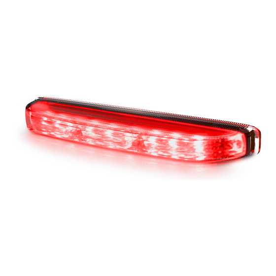
CD5051 Series Directional LEDs
Flash Rate
Temperature Range
See flash pattern charts
-30°C (-22ºF) to 50°C (122ºF)
Page 1 of 8
Advertisement
Table of Contents

Related Manuals for Code 3 CD5051 Series


Summary of Contents for Code 3 CD5051 Series
- Page 1 Installation and Operation Instructions CD5051 Series Directional LEDs IMPORTANT! Read all instructions before installing and using. Installer: This manual must be delivered to the end user. WARNING! Failure to install or use this product according to manufacturers recommendations may result in property damage, serious injury, and/...
- Page 2 The CD5051 Series of directional LED light heads are self flash- ing. All wiring should be stranded and a minimum of 22 AWG. The positive line must have an in-line 3 Amp slow-blow fuse for each directional as shown in FIGURE 4.
- Page 3 Flash Pattern Selection: The CD5051 series directionals can be configured to flash the following patterns by momentarily applying ground to the blue wire. Holding the blue wire to the ground wire for 2-3 seconds will toggle the unit to the previous pattern. The unit must be powered through the power and ground wires to allow pattern selection.
- Page 4 CD5051XX DUAL COLOR FLASH PATTERN CHART attern Description Phase FPM SAE J595* CA T13** Red & White Red Wire White Wire Wires 1 - Default Single Flash - Color 1 Class 1 Class B Single Flash - Color 1 Class 1 Class B Single Flash - Alternating Color 1 &...
- Page 5 CD5051XX DUAL COLOR FLASH PATTERN CHART (Continued) Pattern Description Phase FPM SAE J595* CA T13** Red & White Red Wire White Wire Wires Triple Flash - Color 1 Class 1 Class B Triple Flash - Color 1 Class 1 Class B Triple Flash - Alternating Color 1 &...
- Page 6 Notes: Page 6 of 8...
- Page 7 Notes: Page 7 of 8...
- Page 8 *Code 3®, Inc. reserves the right to repair or replace at its discretion. Code 3®, Inc. assumes no responsibility or liability for expenses incurred for the removal and /or reinstallation of products requiring service and/or repair.;...
Need help?
Do you have a question about the CD5051 Series and is the answer not in the manual?
Questions and answers