
Related Manuals for ProSoft PLX51-PBS


Summary of Contents for ProSoft PLX51-PBS
- Page 1 PLX51-PBS PROFIBUS DP Slave to EtherNet/IP™ or Modbus ® Gateway August 7, 2020 USER MANUAL...
-
Page 2: Your Feedback Please
Neither ProSoft Technology nor any of its affiliates or subsidiaries shall be responsible or liable for misuse of the information contained herein. Information in this document including illustrations, specifications and dimensions may contain technical inaccuracies or typographical errors. -
Page 3: Table Of Contents
Installing the Configuration Software ............... 13 Network Parameters ....................14 GSD File Management ....................18 Creating a New Project ....................21 PLX51-PBS Parameters ....................23 General ....................... 23 Modbus ......................24 Modbus Addressing ................... 25 PROFIBUS Slave Configuration ................27 Logix ........................ - Page 4 Preface Slot Configuration – Modbus Specific ..................40 Start-up Parameters ................... 41 DPV1 Objects ..................... 42 DPV1 Alarms ...................... 44 Module Download ..................... 46 Logix Configuration ....................47 EDS AOP (Logix V21+) ..................47 Generic Module Profile (Logix Pre-V21) ............50 Multi-Connection ....................
- Page 5 Preface PLX51-PBS ......................83 General ............................84 Slave Status ..........................87 Modbus Statistics ........................88 Ethernet Clients ........................89 TCP/ARP ............................ 89 Device Status ...................... 90 General – Slave Mode ....................... 91 Statistics ............................ 93 PROFIBUS Packet Capture ..................96 Modbus Packet Capture ....................
-
Page 6: Preface
Slave to EtherNet/IP™ or Modbus Gateway module. The module will hereafter be collectively referred to as PLX51-PBS. The PLX51-PBS can operate only as one or more (emulates up to 10) PROFIBUS DPV0/DPV1 Slaves. This allows EtherNet/IP or Modbus devices to exchange process, alarming, and diagnostic data with other PROFIBUS DP Master(s). -
Page 7: Features
Preface FEATURES The PLX51-PBS has two Ethernet ports allowing for either a Linear or Ring (Device Level Ring – DLR) Ethernet topology. The Ethernet ports can also be set up for port mirroring allowing for better fault analysis. The PLX51-PBS can synchronize to an NTP Server, allowing for automatic time synchronization. -
Page 8: Additional Information
Resource Link PLX50 Configuration www.prosoft-technology.com Utility Installation PLX51-PBS User Manual www.prosoft-technology.com PLX51-PBS Datasheet Table 1.1 - Additional Information SUPPORT Technical support is provided via the Web (in the form of user manuals, FAQ, datasheets etc.) to assist with installation, operation, and diagnostics. -
Page 9: Installation
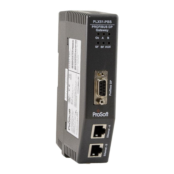
2. INSTALLATION MODULE LAYOUT The PLX51-PBS has one RS485 PROFIBUS DP port as well as two Ethernet ports. The Ethernet cable must be wired according to industry standards, which can be found in the Additional Information section of this document. - Page 10 At the bottom of the module, there is one 3-way power connector. Figure 2.2 – PLX51-PBS Power connector The PLX51-PBS has an input voltage range of 10 to 36 VDC, applied to the module via the power connector. The power connector also provides an Earth connection for the PLX51-PBS.
-
Page 11: Module Mounting
Installation MODULE MOUNTING The PLX51-PBS provides a DIN rail clip to mount onto a 35mm DIN rail. Figure 2.4 - DIN rail specification The DIN rail clip is mounted at the back of the module as shown in the figure below. Use a flat screw driver to pull the clip downward. -
Page 12: Profibus Dp Port (Rs485)
Installation PROFIBUS DP PORT (RS485) The PROFIBUS DP port uses a female DB9 connector. This provides connection for the communication conductors, cable shielding, and +5Vdc output power. Figure 2.6 – PLX51-PBS PROFIBUS DP (RS485) DB9 connector Signal Description Not connected... -
Page 13: Setup
Setup 3. SETUP INSTALLING THE CONFIGURATION SOFTWARE All PLX51-PBS network setup and configuration is done in the ProSoft PLX50 Configuration Utility. This software can be downloaded from: www.prosoft-technology.com Figure 3.1. - ProSoft PLX50 Configuration Utility Environment Page 13 of 111... -
Page 14: Network Parameters
Setup NETWORK PARAMETERS The PLX51-PBS has DHCP (Dynamic Host Configuration Protocol) enabled as factory default. Thus, a DHCP server must be used to provide the module with the required network parameters (IP address, subnet mask, etc.). There are a number of DHCP utilities available, however it is recommended that the DHCP server in the PLX50 Configuration Utility is used. - Page 15 Figure 3.5. - Successful IP address assignment It is possible to force the PLX51-PBS back into DHCP mode by powering up the device with DIP switch 2 set to the On position. A new IP address can then be assigned by repeating the previous steps.
- Page 16 Setup In addition to the setting the IP address, a number of other network parameters can be set during the DHCP process. These settings can be viewed and edited in the PLX50 Configuration Utility Application Settings, in the DHCP Server tab. Once the DHCP process is complete, the network settings can be set using the Ethernet Port Configuration via the Target Browser.
- Page 17 Setup Right-clicking on a device, reveals the context menu, including the Port Configuration option. Figure 3.8. - Selecting Port Configuration The Ethernet port configuration parameters can be modified using the Ethernet Port Configuration window. Figure 3.9. - Port Configuration Alternatively, these parameters can be modified using Rockwell Automation’s RSLinx software.
-
Page 18: Gsd File Management
Each PROFIBUS device has a GSD file that is required to provide information needed to configure the device for data exchange. The PLX50 Configuration Utility manages the GSD library which is used for adding devices to the PLX51-PBS. 1 The GSD File Management Tool is opened by selecting GSD File Management under the Tool menu in the configuration utility. - Page 19 Setup 3 To add a GSD file, select the Add option under the GSD File menu. Figure 3.12 – GSD File Adding 4 Select the required GSD file and click O Figure 3.13 – Adding GSD File 5 Once the file has been selected, the GSD File Management tool adds the slave device to the device list and recompile the GSD catalog.
- Page 20 Setup A GSD catalog can be exported from another PLX50 Configuration Utility by exporting the GSD catalog from one PLX50 Configuration Utility, and importing it in another. This is done by selecting either Import or Export under the Catalog menu as shown below: Figure 3.14 –...
-
Page 21: Creating A New Project
Setup CREATING A NEW PROJECT 1 Before you configure the module, a new PLX50 Configuration Utility project must be created. Under the File menu, select New. Figure 3.15 - Creating a new project 2 A PLX50 Configuration Utility Design Tool project is created, showing the Project Explorer tree view. - Page 22 Setup 4 In the Add New Device window, the PLX51-PBS and click the O button. Figure 3.17 – PLX51-PBS 5 The device appears in the Project Explorer tree and its configuration window opened. The device configuration can be reopened by double-clicking the module in the Project Explorer tree, or right-clicking the module and selecting Configuration.
-
Page 23: Plx51-Pbs Parameters
Mode The PLX51-PBS can operate in one of two modes: Quiet - Connects the PLX51-PBS to an active bus and runs a DP packet capture. The PLX51-PBS will not communicate on the DP Bus, but rather only listen. Slave - In this mode, the PLX51-PBS will emulate multiple PROFIBUS Slave devices. -
Page 24: Modbus
The time the module will wait for a Modbus response (Modbus Master only) Enable Modbus When enabled, the PLX51-PBS will be able to read from, and write to, multiple Auxiliary Mapping Modbus Slaves by using the Modbus Auxiliary Map tab. -
Page 25: Modbus Addressing
Setup ODBUS DDRESSING The Modbus Addressing configuration is shown in the figure below. Figure 3.21 – PLX51-PBS Modbus Addressing configuration The Modbus configuration consists of the following parameters: Parameter Description Base Offset Type Base Address Offset Type Modbus (Base 0) – Conventional Modbus addressing where the first address is 0. - Page 26 Setup Slave Device Enables Enables the individual Slave Device Enable bits. When Enabled, the module can enable/disable each slave device through the use of the Device Control Register. When Disabled, all slave devices are enabled. Slave Device Control Enables the Slave Device Control (Alarm Triggers). When Enabled, the module can generate Alarms for each slave device through the use of the Device Control Register.
-
Page 27: Profibus Slave Configuration
Setup PROFIBUS S LAVE ONFIGURATION The PLX51-PBS PROFIBUS slave configuration is opened by either double-clicking on the module in the tree, or right-clicking the module and selecting Configuration. Then select the PROFIBUS tab. Figure 3.22 – PLX51-PBS PROFIBUS slave configuration... -
Page 28: Logix
This section is used when the Primary Interface in the General tab is set to EtherNet/IP. The PLX51-PBS Logix configuration is opened by either double-clicking on the module in the tree, or right-clicking the module and selecting Configuration. Then select the Logix tab. - Page 29 Setup To browse to a controller path, select the B … button to open the Target Browser. ROWSE Then select a Logix controller and click Ok. The path updates automatically. Figure 3.24 – Target Browser – Selecting Logix controller Page 29 of 111...
-
Page 30: Advanced
Setup DVANCED The PLX51-PBS Advanced configuration is opened by either double-clicking on the module in the tree, or right-clicking the module and selecting Configuration. Then select the Advanced tab. Figure 3.25 – PLX51-PBS Advanced configuration The Advanced configuration consists of the following parameters:... -
Page 31: Adding Profibus Dp Devices
Setup ADDING PROFIBUS DP DEVICES The user will need to add each PROFIBUS device to the PLX51-PBS. Each device can then be individually configured. This is done by right-clicking on PROFIBUS Devices in the tree and selecting Add PROFIBUS Device. -
Page 32: General
Setup ENERAL The General tab is shown in the following figure: Figure 3.27 – General configuration parameters The General configuration consists of the following parameters: Parameter Description Instance Name The device instance name which will be used to create the Tag names and UDTs in Logix. -
Page 33: Profibus Configuration
Setup PROFIBUS C ONFIGURATION The PROFIBUS Configuration tab is shown in the following figure: Figure 3.28 – PROFIBUS Configuration parameters The PROFIBUS configuration consists of the following parameters: Parameter Description Node Address This is the station address configured for the added device. This is the address the PROFIBUS Master will use to look for and configure the device for Data Exchange. -
Page 34: Dpv1
Setup DPV1 The DPV1 configuration tab is shown in the following figure: Figure 3.29 – DPV1 configuration parameters The DPV1 configuration consists of the following parameters: Parameter Description Indicates if the slave supports DPV1 Class 1 access (read and write) or Enable DPV1 alarms. -
Page 35: User Parameters
Setup ARAMETERS (PLX51-PBM Master mode only) The User Parameters for the device is shown in the figure below. The User Parameter information is extracted from the device GSD file. Page 35 of 111... -
Page 36: Slot Configuration
Setup ONFIGURATION Each slave device can have multiple slots that can be configured. A slot can be a place holder for a process variable or a placeholder for a specific piece of hardware. Figure 3.30 – Field Device Slot configuration start To add a module, select the Add Module button. - Page 37 Setup The module will be added to the Slot configuration. The layout of the slot configuration differs slightly depending on whether Logix or Modbus has been selected as the Primary Interface. Figure 3.32 – Slot configuration – (Logix) Figure 3.33 – Slot configuration – (Modbus) Page 37 of 111...
-
Page 38: Slot Configuration - General
Setup SLOT CONFIGURATION - GENERAL Each module added can consist of one or more Data Points. In the example below the module has two Data Points, one Input and one Output. The description of each is based on the module name (from GSD file) but can be edited by the user. - Page 39 Setup After adding a new Data Point, the following should be configured: Description Data Point Type (Input, Output, None) Data Type Byte Length Figure 3.36 – Configuring Data Points After updating the Data Type, the Byte Length will be set to match the selected Data Type. By modifying the Byte Length thereafter, an array of that Data Type can be configured.
-
Page 40: Slot Configuration - Logix Specific
Setup SLOT CONFIGURATION – LOGIX SPECIFIC When using Logix as the Primary Interface, the PROFIBUS Data Points will be packed and padded to match a device specific UDT. All the Inputs will be collated together and then all the Outputs. NOTE: It is important that the Data Point Descriptions do not contain any illegal characters and are not duplicated within a device. -
Page 41: Start-Up Parameters
Setup TART ARAMETERS PLX51-PBM Master mode only. The device start-up parameter information is shown in the figure below. Page 41 of 111... -
Page 42: Dpv1 Objects
Setup DPV1 O BJECTS The DPV1 Objects configuration tab is shown in the following figure: Figure 3.39 – DPV1 Objects configuration parameters – Logix Figure 3.40 – DPV1 Objects configuration parameters – Modbus The DPV1 configuration consists of the following parameters: Parameter Description Slot... - Page 43 Setup NOTE: The logix controller path must be correctly set for the tags to show up in the browser. Figure 3.41 – DPV1 Objects Tag Browsing Page 43 of 111...
-
Page 44: Dpv1 Alarms
Setup DPV1 A LARMS The DPV1 Alarms configuration tab is shown in the following figure: NOTE: The Size of the DPV1 Alarm must be greater than 4 or the alarm triggering will not execute. Figure 3.42 – DPV1 Alarms configuration parameters (Logix) Figure 3.43 –... - Page 45 Setup NOTE: The PROFIBUS DP Master connected to the PLX51-PBS will be able to configure the following alarms: Diagnostic Alarm Process Alarm Pull Plug Alarm Status Alarm Update Alarm Manufacturer Specific Alarm Page 45 of 111...
-
Page 46: Module Download
Setup MODULE DOWNLOAD Once the PLX51-PBS configuration is complete, it must be downloaded to the module. The configured IP address of the module is used to connect to the module. 1 To initiate the download, right-click on the module and select the Download option. -
Page 47: Logix Configuration
Setup LOGIX CONFIGURATION The PLX51-PBS can be easily integrated with Allen-Bradley Logix family of controllers. Integration with the Logix family in Studio5000 makes use of the EDS Add-On-Profile (AOP) or a Generic Module Profile. EDS AOP (L V21+) OGIX Before the module can be added to the tree the module’s EDS file must be registered. - Page 48 Setup The module selection dialog will open. To find the module more easily, use the Vendor filter to select only the ProSoft Technology modules as shown in the figure below. Figure 3.49 – Selecting the module Page 48 of 111...
- Page 49 Setup Locate and select the PLX51-PBS module and select the Create option. The module configuration dialog will open, where the user must specify the Name and IP address as a minimum to complete the instantiation. Figure 3.50 – Module instantiation Once the instantiation is complete the module will appear in the Logix IO tree.
-
Page 50: Generic Module Profile (Logix Pre-V21)
Figure 3.54 – Modified Logix Routine from PLX50CU for Generic Module Profile When using Logix versions prior to version 21, then the PLX51-PBS module must be added to the RSLogix 5000 I/O tree as a generic Ethernet module. This is achieved by right clicking on the Ethernet Bridge in the RSLogix 5000 and selecting New Module after which the ETHERNET- MODULE is selected to be added as shown in the figure below. - Page 51 Setup The user must enter the IP address of the PLX51-PBS module that will be used. The assembly instance and size must also be added for the input, output, and configuration in the connection parameters section. Figure 3.56 - RSLogix 5000 New Module parameters for PLX51-PBS module...
- Page 52 Figure 3.58 - Connection module properties in RSLogix 5000 Once the module has been added to the RSLogix 5000 I/O tree the Logix controller will be ready to connect to the PLX51-PBS with a Class 1 connection. Figure 3.59 – RSLogix 5000 I/O module tree...
-
Page 53: Multi-Connection
Setup ULTI ONNECTION The PLX51-PBS supports up to four Class 1 (cyclic data exchange) connections. This will allow the user to have more field devices per PLX51-PBS because more data can be exchanged between the Logix controller and the PLX51-PBS. -
Page 54: Logix Mapping
The PLX50 Configuration Utility will generate the required UDTs and Routines (based on the PLX51-PBS configuration) to map the required PROFIBUS Slave input and output data. The user will need to generate the required Logix and UDTs by right-clicking on the module in the PLX50 Configuration Utility and selecting the Generate Logix L5X option. - Page 55 Setup This L5X file can now be imported in to the Studio 5000 project by right-clicking on a suitable Program and selecting Add, and then Import Routine. Figure 3.64 – Importing the L5X file into Studio 5000 In the file open dialog select the previously created L5X file and accept the import by pressing The import will create the following: ...
- Page 56 Setup Figure 3.66 – Imported Logix Objects A number of PLX51 specific (UDT) tags are created. The General Control tag is used to enable the individual slave devices. The Master Control and Redundancy Control tags are not utilized. Figure 3.67 – General Control tag Page 56 of 111...
- Page 57 Setup The General Status tag displays the status of the PROFIBUS Slave, including arrays to show the LiveList, Data Exchange Active, Alarm and Diagnostic pending status of each slave device. Figure 3.68 – General Status tag There is also a tag created for each configured slave device. The structure of which comprises the following: ...
-
Page 58: Sd Card
SD Card 4. SD CARD The PLX51-PBS supports an SD Card (see below) that can be used for disaster recovery. The SD Card can be pre-loaded with the required firmware and/or application configuration. Figure 4.1 – Module Side View – SD Card Slot NOTE: The user will need to ensure that the SD Card has been formatted for FAT32. -
Page 59: Firmware
SD Card FIRMWARE The user can copy the required firmware (which can be downloaded from the ProSoft website) onto the root directory of the SD Card. Figure 4.2 – SD Card – Firmware file NOTE: The filename must not be changed. -
Page 60: Configuration
SD Card CONFIGURATION The user can add the configuration file to the SD Card root directory in one of two ways: Manually or PLX50 Configuration Utility. During boot-up, the module will determine if the configuration on the SD card is different than the module’s current configuration (or no configuration). -
Page 61: Manual Copy
ANUAL Once the user has configured the application in the PLX50 Configuration Utility, the user can copy this file into the root directory of the SD Card. Right-Click on the PLX51-PBS icon and select E XPORT ONFIGURATION Figure 4.4 – Configuration Export for SD Card Figure 4.5 –... -
Page 62: Plx50 Configuration Utility
When the SD Card has been inserted into the module and the user is online in PLX50 Configuration Utility, the user can directly upload the configuration onto the SD Card. Right-Click on the PLX51-PBS icon and select S SD C ONFIGURATION TO This copies the configuration from the module directly to the SD Card. -
Page 63: Operation
Operation 5. OPERATION LOGIX OPERATION The PLX51-PBS can exchange data with a Logix controller by establishing a Class 1 connection. PROFIBUS DP - S LAVE NOTE: The imported Logix routine (generated by the PLX50 Configuration Utility) copies the module’s input and output assembly of each connection to the structured input and output assemblies. - Page 64 1 – PLX51-PBS has been successfully configured. 0 – PLX51-PBS is not configured. Owned Indicates if the PLX51-PBS is owned by a Logix Controller with a connection count similar to what has been configured in PLX50CU. 1 – PLX51-PBS is connected.
- Page 65 Operation DeviceAlarmPendingFlags Indicates the nodes that have an alarm pending on the local PROFIBUS network. Each bit represents a node. When the specific bit is set ‘1’ then the device has an alarm pending that must be unloaded and when the bit is off ‘0’...
-
Page 66: General Control
Monitoring faults (e.g. configured device not found) can be done by viewing the LEDs of the PLX51-PBS (see the Diagnostics section for more details), by going online in the PLX50 Configuration Utility and viewing the PLX51-PBS Slave and Device Diagnostics, or by viewing the input assembly of the PLX51-PBS in Logix. -
Page 67: Status And Dpv0 Data Exchange
The DPV0 data is exchanged with Logix using the Class 1 EtherNet/IP connection. The device- specific tag contains all the input and output data fields, as well as important control and status information. Figure 5.3 – PLX51-PBS Slave Device-Specific tag Description PLX51PBS.Input.Status. - Page 68 0 – The mapping for the output data is correct. 1 – There is a mapping mismatch in the output data. SlaveClearOpMode When the PLX51-PBS is in Slave Mode; this indicates that the respective slave is in fieldbus CLEAR mode (received from the DP Master on the network).
- Page 69 The station number entered by the Logix mapping code of the specific slave device. AlarmTrigger When the PLX51-PBS is in Slave Mode; when this bit changes from 0 to 1, it will trigger an alarm notification to the DP Master. DeviceMappingCRC The checksum of the mapping that was applied by the generated Logix code used to verify if the mapping being used is valid.
-
Page 70: Dpv1 Class 1 Messaging (Ms1)
When the PROFIBUS Master sends a DPV1 read/write command for the configured slot and index, the PLX51-PBS accesses the configured Logix tag to provide the required data. The data to be written or read is extracted from the Logix SINT array. This array was configured in the DPV1 objects of the device configuration window. -
Page 71: Alarming
Operation ALARMING The PLX51-PBS slave feature supports DPV1 Alarming. You can trigger an alarm from the Logix device output assembly, which will notify the PROFIBUS Master that a new alarm has been generated. When the PROFIBUS Master sends a DPV1 alarm read command, the PLX51-PBS accesses the configured Logix tag to provide the required data for the specific alarm. - Page 72 Operation The format of the DPV1 Alarm data in the Logix SINT array is shown below: Byte Byte Description Alarm Parameter Offset Size Alarm Length Length of the Alarm data at the bottom of the table. Refer to the PROFIBUS Specification EN 50170 for information regarding the diagnostics.
-
Page 73: Modbus Operation
Operation MODBUS OPERATION When the PLX51-PBS has been setup for Modbus communication it will exchange data with a remote Modbus device. Depending on the Primary Interface selection, the PLX51-PBS will either function as a Modbus Master or Modbus Slave. NOTE: When configured as a Modbus Slave the Modbus Master device will need to read and write all required data from the configured Modbus address ranges. -
Page 74: Dpv0 Data Exchange
Operation CS Offset Description Slave Device Status Online 544 + (16 x [Station Address]) Data Exchange Active 545 + (16 x [Station Address]) Ident Mismatch 546 + (16 x [Station Address]) Disabled by Output Assembly 547 + (16 x [Station Address]) Device Error 548 + (16 x [Station Address]) Alarm Pending... -
Page 75: Dpv1 Class 1 Messaging (Ms1)
Holding Register Addresses (see below). Figure 5.9 – DPV1 Objects Holding Register address Once the PROFIBUS Master reads or writes to a DPV1 Class 1 Slot/Index, the PLX51-PBS will use the data located at the configured Modbus Address. NOTE: If the PLX51-PBS has been setup as a Modbus Master then the data will be read or written to the specific Modbus HR address in the target device when the DPV1 Message request is received on the PROFIBUS network. - Page 76 Operation Once the alarm has been triggered the PLX51-PBS will read the alarm data from the configured Modbus Holding Register address range and add it to the PROFIBUS diagnostics (which will then be read by the PROFIBUS Master) as shown below.
-
Page 77: Modbus Auxiliary Map
Modbus tab, and configured for Modbus Master. This will allow the user to read and/or write any internal PLX51-PBS Modbus Register to any Modbus Slave. Up to 20 Modbus Slaves can be connected and up to 200 mapped items can be configured. - Page 78 Operation Figure 5.11 – PLX51-PBS Modbus Auxiliary Map configuration The Modbus Auxiliary Map configuration consists of the following parameters: Parameter Description Modbus Function This is the Modbus function is the used with the Modbus Slave. Read – Read a Modbus Register (eg. HR, IR, CS, or IS) from a Modbus Slave.
-
Page 79: Firmware Upgrading
Operation FIRMWARE UPGRADING Using the PLX50 Configuration Utility, you can upgrade the PLX51-PBS firmware in the field. 1 In the PLX50 Configuration Utility, go to the Tools menu and select the D EVICE LASH option. Figure 5.12 - DeviceFlash Tool... - Page 80 Operation 3 In the Target Browser window, select the PLX51-PBS’s IP address and click O Figure 5.14 - Select the PLX51-PBS module 4 Once the firmware update is complete, the DeviceFlash option provides the details of the updated module. Figure 5.15 – PLX51-PBS successfully updated.
-
Page 81: Diagnostics
Diagnostics 6. DIAGNOSTICS LEDS The module provides six LEDs for diagnostics purposes as shown below. Figure 6.1 - PLX51-PBS LEDs Description Flashing Green – The module has booted and is running correctly without any application configuration loaded. Solid Green – The module has booted and is running correctly with application configuration loaded. -
Page 82: Module Status Monitoring
Diagnostics MODULE STATUS MONITORING The PLX51-PBS provides a range of statistics that can assist with module operation, maintenance, and fault finding. The statistics can be accessed by the PLX50 Configuration Utility or using the web server in the module. To view the module’s status in the PLX50 Configuration Utility environment, the PLX51-PBS must be online. -
Page 83: Plx51-Pbs
Diagnostics PLX51-PBS The PLX51-PBS Status window is opened by either double-clicking on the Status item in the Project Explorer tree, or by right-clicking on the module and selecting Status. Figure 6.3 - Selecting PLX51-PBS online Status The status window contains multiple tabs to display the current status of the module. -
Page 84: General
Mode of operation of the module. The following states can be returned: Quiet This mode allows you to connect the PLX51-PBS to an active bus and run a DP packet capture. In this mode, the PLX51-PBS will not communicate on the DP Bus, but rather only listen. - Page 85 Indicates the elapsed time since the module was powered-up. Firmware Revision The current PLX51-PBS application firmware revision. Configuration Signature The current PLX51-PBS signature of the configuration. MAC Address Displays the module’s unique Ethernet MAC address. Temperature The internal temperature of the module.
- Page 86 Diagnostics Disabled The NTP time synchronization has been disabled. Locked NTP time synchronization has been enabled and the PLX51-PBS has locked onto the target time server. Not Locked NTP time synchronization has been enabled and the PLX51-PBS has not locked onto the target time server.
-
Page 87: Slave Status
Diagnostics SLAVE STATUS The Slave Status tab displays the following parameters: Figure 6.5 – PLX51-PBS Status monitoring – Slave Status Parameter Description BAUD Rate Current BAUD rate of the PROFIBUS Network. Auto-BAUD If the BAUD rate for the PROFIBUS Network will be automatically detected. -
Page 88: Modbus Statistics
Diagnostics MODBUS STATISTICS The Modbus Statistics tab displays the statistics associated with the Modbus communication and mapping. Figure 6.6 – PLX51-PBS Status monitoring – Modbus Statistics Statistic Description Tx Packet Count The number of Modbus packets sent by the module. -
Page 89: Ethernet Clients
Figure 6.7 – PLX51-PBS Status monitoring – Ethernet Client Statistics TCP/ARP The TCP/ARP tab displays details of the internal Ethernet ARP and TCP lists of the PLX51- PBS. Figure 6.8 – PLX51-PBS Status monitoring – Ethernet TCP / ARP Statistics Page 89 of 111... -
Page 90: Device Status
Diagnostics EVICE TATUS The Device Status window of each PROFIBUS slave device connected to the PLX51-PBS is opened by right-clicking on the specific slave device icon in the PLX50 Configuration Utility tree, and selecting S TATUS Figure 6.9 - Selecting slave status The device status window contains multiple tabs to display the status of the specific slave device. -
Page 91: General - Slave Mode
The slave device is exchanging DPV0 process data with the PROFIBUS DP Master. Enabled/Disabled (Logix) The slave device has been enabled/disabled from DPV0 data exchange from the Logix controller using the PLX51-PBS output assembly. Identity Mismatch The device configured in the PLX50 Configuration Utility and the device online at the specific station address do not match. - Page 92 Diagnostics StationID Mismatch (PLC) The station address entered from the Logix controller using the PLX51-PBS output assembly does not match the station address of the configured slave device. CRC Mismatch (PLC) Indicates the mapping from the Logix controller does not match the configured mapping.
-
Page 93: Statistics
Checksum Failed Packet Count The number of PROFIBUS packets that had a failed checksum. No Reply Count The number of PROFIBUS requests from the PLX51-PBS where the station did not respond. DPV1 Class 1 Read Tx Count The number of PROFIBUS DPV1 Class 1 Read responses sent from the specific device to the PROFIBUS DP Master. - Page 94 Diagnostics DPV1 Class 1 Write Rx Count The number of successful PROFIBUS DPV1 Class 1 Write requests received by the specific device. DPV1 Class 1 Write Err Count DPV1 Class 2 Init Tx Count DPV1 Class 2 Init Rx Count The number of PROFIBUS DPV1 Class 2 Initialize requests received by the specific device.
- Page 95 Diagnostics Initialize Parameter Set Fail The number of parameters that have failed to set after the device has Count been configured for DPV0 data exchange for the specific device. Device Reconfigure Count The number of times the device has been (re)configured for DPV0 data exchange.
-
Page 96: Profibus Packet Capture
PROFIBUS PACKET CAPTURE The PLX51-PBS allows you to capture the PROFIBUS traffic for analysis. 1 To invoke the capture of the module, right-click on the PLX51-PBS icon and double- click on the DP P item in the Project Explorer tree. - Page 97 Diagnostics 3 When the capture process is stopped, the PROFIBUS capture is presented as shown below. Figure 6.14 - PROFIBUS Packet Capture complete The captured PROFIBUS packets are tabulated as follows: Statistic Description Index The packet index incremented for each packet sent or received. Time The time is measured in microseconds (us) and is started at a fraction of a second and continued until the packet capture is done.
- Page 98 Diagnostics 4 The packet capture can be saved to a file for further analysis by selecting the S button on the toolbar. 5 Previously saved PROFIBUS Packet Capture files can be viewed by selecting the PROFIBUS P option in the Tools menu. ACKET APTURE IEWER...
-
Page 99: Modbus Packet Capture
Diagnostics MODBUS PACKET CAPTURE The PLX51-PBS allows you to capture the Modbus traffic for analysis. 1 To invoke the capture of the module, right-click on the PLX51-PBS icon and double- click on the M item in the Project Explorer tree. - Page 100 Diagnostics 3 When the capture process is stopped, the Modbus capture is presented as shown below. It will keep capturing until you press S Figure 6.18 - Modbus Packet Capture complete The captured Modbus values are tabulated as follows: Statistic Description Index The packet index incremented for each packet sent or received.
-
Page 101: Module Event Log
Diagnostics MODULE EVENT LOG The PLX51-PBS logs various diagnostic records to an internal event log. These logs are stored in non-volatile memory and can be displayed using the PLX50 Configuration Utility or via the web interface. To view them in the PLX50 Configuration Utility, select the E... -
Page 102: Web Server
WEB SERVER The PLX51-PBS provides a web server for diagnostics. This allows for connectivity to the module without the use of the PLX50 Configuration Utility, Logix, or Modbus device to view various the diagnostics of the module. NOTE: The web server is read-only and thus no parameters or configuration can be altered from the web interface. -
Page 103: Technical Specifications
Technical Specifications 7. TECHNICAL SPECIFICATIONS DIMENSIONS Below are the enclosure dimensions. All dimensions are in millimeters. Figure 7.1 – PLX51-PBS enclosure dimensions Page 103 of 111... -
Page 104: Electrical
Technical Specifications ELECTRICAL Specification Rating Power requirements Input: 10 to 36V DC Power consumption Maximum: 85mA @ 24V => 2.04W Connector 3-way terminal Conductors 24 to 18 AWG Enclosure rating IP20, NEMA/UL Open Type Temperature -20 to 70 °C Earth connection Yes, terminal based Emissions IEC61000-6-4... -
Page 105: Profibus Dp
BAUD Rate supported 9.6 kbps 19.2 kbps 45.45 kbps 93.75 kbps 187.5 kbps 500 kbps 1.5 Mbps 3 Mbps 6 Mbps 12 Mbps Table 7.3 – PROFIBUS DP specification AGENCY APPROVALS AND CERTIFICATIONS Please visit our website: www.prosoft-technology.com Page 105 of 111... -
Page 106: Profibus Dp
PROFIBUS DP 8. PROFIBUS DP INTRODUCTION PROFIBUS is a vendor-independent, open fieldbus standard for a wide range of applications in manufacturing, process and building automation. Vendor independence and openness are guaranteed by the PROFIBUS standard EN 50 170. With PROFIBUS, devices of different manufacturers can communicate without special interface adjustments. -
Page 107: Profibus Master And Slave
PROFIBUS DP PROFIBUS PA PROFIBUS PA is designed especially for process automation. It permits sensors and actuators to be connected on one common bus line through a dedicated DP/PA gateway or link between the PROFIBUS DP and PROFIBUS PA networks, even in intrinsically-safe areas. PROFIBUS PA permits data communication and power over the bus using a 2-wire technology according to the international standard IEC 1158-2. -
Page 108: Profibus Master Class 1 (Dpm1) Or Class 2 (Dpm2)
PROFIBUS DP PROFIBUS MASTER CLASS 1 (DPM1) OR CLASS 2 (DPM2) PROFIBUS DP Master Class 1 (DPM1) A class 1 master handles the normal communication or exchange of data with the slaves assigned to it. This is typically a PLC. It uses cyclic communication to exchange process data with its associated slaves. -
Page 109: Acyclic Communication
PROFIBUS DP ACYCLIC COMMUNICATION In addition to the cyclic data exchange, the PROFIBUS protocol has the option of acyclic communication. This service is not configured. There are 2 different communication channels possible between the requested master and the slave: o MS1 channel (MS1 connection): can only be established if cyclic data exchange is taking place between that master (DPM1) and the slave o MS2 channel (MS2 connection): is possible with several masters simultaneously, but the connection must be established explicitly by the master. -
Page 110: Profibus Dp Cable Description
1000 Table 9.3 – PROFIBUS DP cable length PROFIBUS DP CONNECTOR DESCRIPTION DB9 Pin Description DB9 Pin# DB9 Termination with PLX51-PBS Chassis ground Reserved Data+ / B In case of termination, connect this pin to Pin 8 (Data - / A) with 220 ohm resistor... -
Page 111: Support, Service & Warranty
Configuration/Debug status information LED patterns Details about the interfaced serial, Ethernet or Fieldbus devices Note: For technical support calls within the United States, ProSoft’s 24/7 after-hours phone support is available for urgent plant-down issues. Europe / Middle East / Africa Regional Office North America (Corporate Location) Phone: +1.661.716.5100...
Need help?
Do you have a question about the PLX51-PBS and is the answer not in the manual?
Questions and answers