Table of Contents
Advertisement
Quick Links
Advertisement
Table of Contents

Related Manuals for Meyer's 435 Tandem


Summary of Contents for Meyer's 435 Tandem
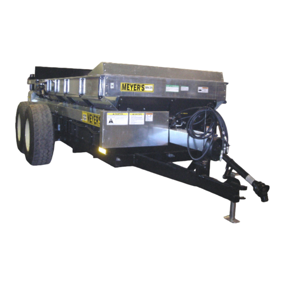
- Page 1 INSTRUCTION AND PARTS BOOK NO. 10-1 HEAVY DUTY MANURE SPREADERS MODEL 435 Tandem operate this Spreader until you have DO NOT read this book repair or clean this Spreader while NEVER PTO is engaged Manufactured in DORCHESTER, WISCONSIN by MEYER’S EQUIPMENT MFG.
-
Page 2: Introduction
INTRODUCTION Congratulations on the purchase of your new Meyer’s The serial number plate is found on the front hitch Manure Spreader. With its optional equipment this is weldment, below the rear end of the PTO drive shaft. the simplest, most flexible system on the market For information on ordering repair parts, refer to the today. -
Page 3: Table Of Contents
TABLE OF CONTENTS INTRODUCTION ................................2 SAFETY ..................................4 MANURE SPREADER SAFETY........................... 8 MANDATORY SAFETY SHUTDOWN PROCEDURE ....................9 PRE-OPERATION ..............................10 General ..................................10 Tractor Hookup ................................ 10 Tractor Requirements ............................10 Tractor Size ................................. 10 Tractor Towing Size Requirements ........................10 Material Estimated Weight Per Cubic Foot ...................... -
Page 4: Safety
SAFETY A brief definition of signal words that may be used in WARNING: Indicates a potentially hazardous this manual: situation that, if not avoided, could result in death or serious injury, and includes hazards that are exposed DANGER: Indicates an imminently hazardous when guards are removed. - Page 5 Model 435 Page 5...
- Page 6 DECAL A. PART NO. 3000 DECAL B. PART NO. SW404-1 DECAL C. PART NO. 3001 DECAL D. PART NO. SW104 DECAL E. PART NO. SW102 DECAL F. PART NO. SW406 DECAL G. PART NO. SW404 DECAL H. PART NO. 3006 DECAL I.
- Page 7 DECAL L. PART NO. 3002 DECAL M. PART NO. SW2001 DECAL O. REFECTIVE TAPE RED PART NO. PM17-5915 DECAL N. PART NO. SW2000 DECAL O. REFECTIVE TAPE YELLOW PART NO. PM17-5910 DECAL Q. PART NO. 3009 DECAL R. PART NO. 3008 START UP PROCEDURE 1.
-
Page 8: Manure Spreader Safety
MANURE SPREADER SAFETY CAUTION THERE ARE INHERENT HAZARDS ASSOCIATED WITH THE OPERATION OF A MANURE SPREADER. FOR YOUR SAFETY: • Never Enter Spreader Box While In Operation For Any Reason. • Only Properly Instructed People Should Operate The Spreader. Do Not Allow Children Or Inexperienced Persons To Operate Spreader. -
Page 9: Mandatory Safety Shutdown Procedure
MANDATORY SAFETY SHUTDOWN PROCEDURE BEFORE unclogging, cleaning, adjusting, lubricating or servicing the unit: 1. Disengage the tractor PTO. 2. Shut off the tractor engine, remove the ignition key and take it with you. 3. Wait for all movement to stop. 4. -
Page 10: Pre-Operation
PRE-OPERATION GENERAL 2. The PTO drive shaft assembly is designed to operate with tractors conforming to the industry Read the entire Owner’s Manual before attempting to standard shown on Figure 1 for 540 RPM PTO operate this manure spreader. Before attempting any output. -
Page 11: Tractor Hookup
NOTE: Heaped loads have significantly higher a tension screw adjustment to regulate force to capacities resulting in increased weight and higher retain settings, Figure 3. center of gravity, requiring extra precaution during 3. Connect the two hydraulic hoses for the end gate operation. -
Page 12: Transporting
Use Safety Chain TRANSPORTING 1. Check for traffic constantly. Be sure you can see CAUTION that no one is attempting to pass you and that all A safety chain should be installed to retain the traffic is sufficiently clear from you before making connection between tractor (or other towing vehicle) any turns. -
Page 13: Operation
OPERATION during spreading, use precautions on slopes and DANGER hills where you will experience a loss of traction by Never enter the spreader box for any reason without traveling over ground with previously spread first disconnecting PTO shaft from tractor. Do not allow manure. -
Page 14: Hydraulic End Gate Operation
Lower the jack to remove load from the tractor drawbar HYDRAULIC END GATE OPERATION and unhook the hitch. MANDATORY SAFETY SHUTDOWN PROCEDURE BEFORE unclogging, cleaning, adjusting, lubricating or servicing the unit: 1. Disengage the tractor PTO. 2. Shut off the tractor engine, remove the Ignition key and take it with you. -
Page 15: Maintenance, Lubrication & Adjustments
MAINTENANCE, LUBRICATION & ADJUSTMENTS 1. Allow the spreader to completely clean out the last DANGER load. It is not safe to clean or service the spreader with 2. Hose off all manure from the spreader, particularly power operating. PTO drive and hydraulics must be getting the end gate mechanisms clean. -
Page 16: Shear Pin Hub Maintenance
FIGURE 9. FRONT DRIVE FIGURE 7. APRON DRIVE GEARBOX There is a bearing at each end of the shaft connecting the PTO shaft with the front roller chain drive. Grease these bearing one pump, every 8 hours. Figure 10. Lubricate the PTO universal joints with 1 pump of grease every 8 hrs. -
Page 17: Adjustments
FIGURE 10. OVERALL SPREADER VIEW ADJUSTMENTS Apron Chain The apron chain is adjusted by (4) adjuster screws located on the front of the box frame. Figure 10. Adjust the 3/4” screws so the chains are below the axle, see Figure 12. When there is no more adjustment left on the adjuster screws, loosen the nuts on the screws and push the screws in as far as they will go. - Page 18 FIGURE 12. ADJUST APRON CHAIN Page 18 Model 435...
- Page 19 This Page Intentionally Blank. Model 435 Page 19...
-
Page 20: Repair Parts
REPAIR PARTS MAIN FRAME AND BOX PARTS Page 20 Model 435... - Page 21 MAIN FRAME AND BOX PARTS PART NO. DESCRIPTION E01733-435 Upper Left Side Extension, Front E01767-435 Upper Right Side Extension, Front E01763-435 Upper Left Side Extension, Rear E01762-435 Upper Right Side Extension, Rear E01079 Flare Left -Galvanized, 16’ Long E01106 Flare, Right-Galvanized, 16’ E01125-435 Bracket, Upper Extension, LH E01124-435...
-
Page 22: Axles, Wheels, Spindles And Related Parts
AXLES, WHEELS, SPINDLES AND RELATED PARTS Page 22 Model 435... - Page 23 AXLES, WHEELS, SPINDLES AND RELATED PARTS PART NO. QTY. DESCRIPTION E00120-08 Arm Assembly, Drilled For 3" Spindle E00146-00 Spindle, Stress Proof 3" x 20 E00147 Seal, Hub, CR29968 E00148 Bearing, Inside Wheel, 387-A5 E00151 Hub, 758 E01689 Bearing, Outside Wheel, LM501349 E00128 Washer E00129...
-
Page 24: Jack
JACK Page 24 Model 435... - Page 25 JACK PART NO. DESCRIPTION E01956 Jack Assembly -3SM-15-0 E01957 Kit, Handle Repair (consists of a clevis, bolt, crank and handle grip assembly) E01958 1 pr. Gears, Bevel E01959 Kit, Inner Ram (includes inner ram, screw, nut & bearing) E01960 Pin, Hitch E01961 Mount, Weld On Model 435...
-
Page 26: Hydraulic End Gate
HYDRAULIC END GATE Page 26 Model 435... - Page 27 HYDRAULIC END GATE PART NO. DESCRIPTION E01558-10 Frame, End Gate w/ End Gate Insert 435-27 Belt, Side 435-21R Right Belt Support Bracket 435-21L Left Belt Support Bracket E00090-12 Cylinder, End Gate Hydraulic - 3” x 9.75” E00109 Cylinder Seal Kit 639572 E00110 Wiper Seal 1125-6 435-23...
-
Page 28: End Gate Hydraulics
END GATE HYDRAULICS Page 28 Model 435... - Page 29 END GATE HYDRAULICS PART NO. DESCRIPTION E00090-07 Cylinder, End Gate Hydraulic -3" x 10" E00109 Cylinder Seal Kit 639572 E00110 Wiper Seal 1125-6 E00067-04 Male JIC to Male ORB 90° Adapter E02100-10 Hose, Hydraulic 102" E20328 Tee 2703-LN-8 E01577-10 Hose Hydraulic 156" E01582-10 Hose, Hydraulic 152"...
-
Page 30: Front And Side Drive Shaft And Related Parts
FRONT AND SIDE DRIVE SHAFT AND RELATED PARTS Page 30 Model 435... - Page 31 FRONT AND SIDE DRIVE SHAFT AND RELATED PARTS PART NO. DESCRIPTION E01774 Key, Square -3/8x1-3/8" Long E01184 Shaft, Side -191" Long -For Standard Drive & Hydraulic E01181 Key, Square -3/8" x 1-1/2" Long E01187 Guard, Shaft -51-15/16" E01784 Flange 3-Hole 62mm-3 E01782 Bearing, FH206-20G-1-1/4"...
-
Page 32: Apron Parts
APRON PARTS Page 32 Model 435... - Page 33 APRON PARTS PART NO. DESCRIPTION E02026-435 Apron, One Side Complete -#67P11 -21 Slats/245 Links (per side) E02027 Link, 67P11 E02028-435 Slat w/Links, Overall 27.00" O.A. E02005-390 Bearing, Bronze VB-00181 Key, Gearbox 1/2" x 1/2" x 5" E02017 Holder, Bearing E00242-00 Sprocket, Apron -#67-7Tooth E01501-435 Shaft, Apron -2"...
-
Page 34: Apron And Lower Beater Drive
APRON AND LOWER BEATER DRIVE Page 34 Model 435... - Page 35 APRON AND LOWER BEATER DRIVE PART NO. DESCRIPTION E01247-04 Shield, Top E01284-10 Bracket, Main Gear Case E01300 Gear Box, Beater Drive E01272-04 Cover, Main Gear Case Gear Box, Apron Drive (see Separate Listing) E00509-440 Motor, Hydraulic -HB, 2-Bolt w/ Relief 1000psi E00313 Spring Clutch Pull E01250...
-
Page 36: Apron Drive Gear Box
APRON DRIVE GEAR BOX Page 36 Model 435... - Page 37 APRON DRIVE GEAR BOX PART NO. DESCRIPTION VB-00032-440 Housing RT350 9975 VB-00033-440 14551 VB-00034-440 Circlip E 82 9918 VB-00035-440 Gear Z=49 9974 VB-00036-440 Bearing 6015 9982 VB-00037-440 Circlip I 115 9984 VB-00038-440 Pinion Z=12 8670-5 VB-00039 Key 12 x 8 x 30 4174 VB-00040-440 Gear Z=50...
-
Page 38: 5490-0672 Gear Box Complete 540 Rpm Beater Drive Gearbox
5490-0672 GEAR BOX COMPLETE 540 RPM BEATER DRIVE GEARBOX Used 11/13 and Later Page 38 Model 435... - Page 39 5490-0672 GEAR BOX COMPLETE 540 RPM BEATER DRIVE GEARBOX Used 11/13 and Later PART NO. QTY. DESCRIPTION 70-06130 Machined Housing E01302 Machined End Cap E21146-W Bolt 5/16-18x3/4 11-20439 E21144-W Gear DP 4 Teeth 17 71-06100 w/ 11-40608 Spacer E01309-W Cross Shaft Output Shimming Required 03/06 - 10/13 E01879 Snap Ring 24-15269 19-16593...
-
Page 40: 5490-0685 Gear Box Complete 1000 Rpm Beater Drive Gearbox
5490-0685 GEAR BOX COMPLETE 1000 RPM BEATER DRIVE GEARBOX Used 11/13 and Later Page 40 Model 435... - Page 41 5490-0685 GEAR BOX COMPLETE 1000 RPM BEATER DRIVE GEARBOX Used 11/13 and Later PART NO. QTY. DESCRIPTION E0307-13 Housing 70-00166 70-16084 Machined End Cap 11-20439 Screw, 5/16-18 X .88, Grade 5 71-06105 Gear, 21 Teeth/M=5.25 71-06106 Gear Shaft, 14 Teeth/M=5.25 E01309-W Cross Shaft, Output w/ Gear Shimming Required 03/06 - 10/13 E01879...
-
Page 42: E01300W Gear Box Complete 540 Rpm Beater Drive Gearbox
E01300W GEAR BOX COMPLETE 540 RPM BEATER DRIVE GEARBOX Used 03/06 - 11/13 Last Serial No. 18T13 Page 42 Model 435... - Page 43 E01300W GEAR BOX COMPLETE 540 RPM BEATER DRIVE GEAR BOX Used 03/06 - 11/13 Last Serial No. 18T13 PART NO. QTY. DESCRIPTION E01307-W Housing 70-00167 E01302 End Cap A40 -15 E01316 Stamping Cover K155 E01914 Bearing Cone (14137A) E01915 Bearing Cup (14276) E01366 Bearing Cone (13687) E01367...
-
Page 44: 4190-0532 Gear Box Complete 1,000 Rpm Beater Drive Gearbox
4190-0532 GEAR BOX COMPLETE 1,000 RPM BEATER DRIVE GEARBOX First Serial No. 5639007 Last Serial No. 2243513 Used 04/07 - 11/13 Page 44 Model 435... - Page 45 4190-0532 GEAR BOX COMPLETE 1,000 RPM BEATER DRIVE GEARBOX First Serial No. 5639007 Last Serial No. 2243513 Used 04/07 - 11/13 PART NO. DESCRIPTION E01307-W Housing 70-00167 E01302 End Cap A40 -15 E01316 Stamping Cover K155 E01914 Bearing Cone (14137A) E01915 Bearing Cup (14276) E01366...
-
Page 46: Beaters And Related Parts
BEATERS AND RELATED PARTS Page 46 Model 435... - Page 47 BEATERS AND RELATED PARTS PART NO. QTY. DESCRIPTION Gear Box, Beater Drive (see separate listing) E01469-10 Coupler, Coarse Splined E01470 7/16x5" -GR8 Bolt -w/locking nut E01979 Paddle, Beater -SP14 E01473-11 Beater Only (less paddles) 9” Paddle Mount E01987-R Bearing Assy, GRA106RRB w/Flanges And Guard E01987-L Bearing Assy, GRA106RRB w/Flanges E02124...
-
Page 48: Apron Drive Hydraulics
APRON DRIVE HYDRAULICS Page 48 Model 435... - Page 49 APRON DRIVE HYDRAULICS PART NO. DESCRIPTION E00509-440 Motor, Hydraulic -HB, 2-Bolt w/ Relief 1000psi Hose, Flow Line E00484-00 Adapter, JIC to O-Ring 6400-8-10 E00485-00 O-Ring Adapter 6403NWO-10-8 E00486-00 Valve, Motor Flow Control E00487-00 Tee, 6803-8-8 E21458 O-Ring Adapter 6410-12-8 E00489-00 Check Valve, LTF-8-OW Hose, Hydraulic, 8M3K-8FJX-8MP-92"...
-
Page 50: Pto Shaft Assembly
PTO SHAFT ASSEMBLY PART NO. DESCRIPTION E01817 Comp. 14NW Universal Joint Telescoping Assm. w/Guard -232-9952 E01818 Joint and Tube Half Assm. w/Guard -92-9952 E01819 Yoke -1-1/4" Bore End -14011-1240 E01820 14 NW Repair Kit -03-10134 E01821 Yoke & Tube -98-9952 E01822 Nylon Bearing Kit -Bearing &... - Page 51 This Page Intentionally Blank. Model 435 Page 51...
-
Page 52: Limited Warranty Statement
LIMITED WARRANTY STATEMENT Meyer’s Equipment Mfg. Corp. warrants each new Meyer’s E.M.C. product to be free from: defects in material and workmanship. This warranty is applicable only for the normal service life expectancy of the product or components, not to exceed 12 consecutive months from the date of delivery of the new Meyer’s E.M.C. product to the original purchaser.
Need help?
Do you have a question about the 435 Tandem and is the answer not in the manual?
Questions and answers