Table of Contents
Advertisement
Available languages
Available languages
Quick Links
E x t
e r n
e F
E x t
r e i
e r n
g a b
e r
Z e
e
T ü
n t r
r k o
a l v
n t a
e r r
i e g
e l u
n g
Hi-O Technology™
OneSystem
®
IO-Modul N5950
Installations- und Montageanleitung
Installation and mounting instructions
Notice d'installation et de montage
D0085205
k t
A u
ß e
B r a
n t ü
n d
r d r
m e
I n n
ü c
l d e
e n
k e r
t ü r
a n
Z y
l a g
d r ü
l i n
e
d e
c k e
D r
ü c
r k o
r
D r
k e r
n t a
e h
k u
k t
f l ü
E n
p p
g e
t r i e
l u n
l a n
S t a
g e
g
t r i e
V e
t u s
l t
r r i e
b
g e
T ü
l t
r g
e s c
A l a
h l o
r m
s s e
D 0
/ S
n
t ö r
0 8
5 2
u n
g
n o
U S
B
N 5
9 5
0
www.assaabloy.de
DE Seite
EN Page
FR
Page
The global leader in
door opening solutions
2
30
58
Advertisement
Chapters
Table of Contents

Related Manuals for Assa Abloy OneSystem IO-Modul N5950


Summary of Contents for Assa Abloy OneSystem IO-Modul N5950
- Page 1 www.assaabloy.de DE Seite EN Page Page E x t e r n E x t r e i e r n g a b T ü n t r r k o a l v n t a e r r i e g e l u ß...
- Page 2 Geben Sie die Anleitung nach der Montage an den Benutzer und im Falle einer Weiterveräußerung mit dem Produkt weiter. Hi-O Technology™ ist ein eingetragenes Warenzeichen der ASSA ABLOY-Gruppe. Open Source Lizenzen ASSA ABLOY Sicherheitstechnik GmbH hält den Quellcode der im Rahmen von Open Source Lizenzen genutzten Software (zum Beispiel FreeRTOS™, newlib, lwIP) auf...
-
Page 3: Table Of Contents
Inhaltsverzeichnis Produktinformation....4 DIP-Schalter......14 DIP-Schalter 1 –... -
Page 4: Produktinformation
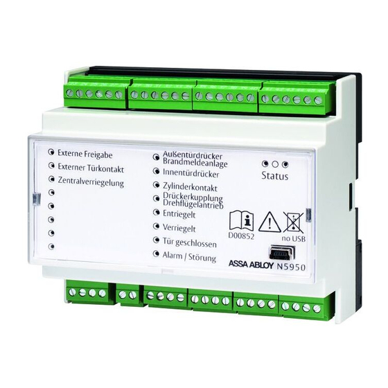
Produktinformation Das OneSystem ® IO-Modul N5950 Das OneSystem ® IO-Modul N5950 (IO-Modul) ist ein Modul zur Verbindung von Hi-O Technology™ Produk- ten, zum Beispiel den OneSystem ® Sicherheitsschlössern, mit konventionellen elektronischen Komponen- ten in Türsystemen, zum Beispiel Zutrittskontrollanlagen und Brandmeldeanlagen. Das OneSystem ®... -
Page 5: Hinweise
Hinweise Zu dieser Anleitung Diese Installations- und Montageanleitung wurde für Elektrotechniker und entsprechend geschultes Personal geschrieben. Lesen Sie diese Anleitung, um das Gerät sicher zu installieren, zu betreiben und die zulässigen Einsatzmöglichkeiten, die es bietet, auszunutzen. Die Anleitung gibt Ihnen auch Hinweise über die Funktion wichtiger Bauteile. Bedeutung der Symbole Gefahr! Sicherheitshinweis: Nichtbeachtung führt zu Tod oder schwerer Verletzung. -
Page 6: Sicherheitshinweise
Sicherheitshinweise Achtung! Eine ungeschützte Verkabelung kann manipuliert werden: Über die Verkabelung werden die elektro- nischen Türkomponenten miteinander verbunden und gesteuert. Die Verkabelung muss zum Schutz vor Manipulationen und Störungen geschützt verlegt werden und darf von außen nicht zugänglich sein. Sachschaden durch Verbindung mit USB-Geräten: Die Anschlussbuchse ist keine USB-Buchse und dient ausschließlich werkseitig zum Verbinden mit Auslesegeräten. -
Page 7: Bestimmungsgemäßer Gebrauch
Bestimmungsgemäßer Gebrauch Das OneSystem ® IO-Modul N5950 (IO-Modul) ist zur digitalen Verbindung von OneSystem ® -Schlössern über Hi-O Technology™ geeignet. Es dient dabei als Verbindung zu konventionellen Geräten, zum Beispiel: · Zutrittskontrolle, · bauseitige Schleusensteuerungen oder · Überwachungssteuerungen. An den potentialbehafteten digitalen Eingängen können externe Steuerungen und Ansteuerkontakte angeschlossen werden. -
Page 8: Eingänge Und Ausgänge
Eingänge und Ausgänge Belegung der Ein- und Ausgänge Das IO-Modul hat bis zu acht digitale, potentialbehaftete Eingänge (Input) und acht potentialfreie Relaisausgänge (Ausgänge) mit Wechselkontakten (Abb. 1). Achtung! Gefahr der Zerstörung, wenn Eingänge potentialbehaftet angesteuert werden: Die digitalen Eingänge dürfen ausschließlich durch potentialfreie Kontakte (Freigabetaster, Relaiskontakt) angesteuert werden. Die Funktion der Ein- und Ausgänge ist für die Nutzung der OneSystem ®... -
Page 9: Eingänge
Eingänge Input – Externe Freigabe An den Eingang kann ein Freigabetaster (oder anderer potentialfreier Ansteuerkontakt) angeschlossen werden („DIP-Schalter“, Seite 14). Je nach angeschlossenen Hi-O Technology™-Geräten aktiviert der Ansteuerkontakt unterschiedliche Prozesse: · ein Motorschloss fährt den Riegel / die Riegel ein, · ein Kupplungsschloss koppelt den Außentürdrücker an, ·... -
Page 10: Ausgänge / Relais
Ausgänge / Relais Kupplungsschloss (DIP 4 = off) Motorschloss (DIP 4 = on) Relais – Außentürdrücker Relais – Brandmeldeanlage Bei einem Schloss mit geteilter Drückernuss: Das Relais schaltet, wenn eine Spannung an Das Relais schaltet, wenn der Außentürdrücker Input – Brandmeldeanlage anliegt. Keine betätigt wird. -
Page 11: Statusmeldungen / Leds
Statusmeldungen / LEDs Über LEDs (Abb. 2) werden die Zustände der Eingänge (Input) und Ausgänge (Relais) angezeigt. Bedeutung : Eingang (Input) leuchtet Der Eingang ist gegen GND geschlossen : Relais (Ausgang) leuchtet Das Relais ist angezogen / aktiv Zusätzlich wird der Status über drei LEDs angezeigt: LED 1 LED 2 Zustand des IO-Moduls... -
Page 12: Konfigurationen
Konfigurationen Gehäuse öffnen Zur Konfiguration muss das IO-Modul-Gehäuse Abb. 3 : geöffnet werden. Gehäuse öffnen Gehäuse öffnen t u s S t a k e r ü c l a g r d r n t ü l d e ß... -
Page 13: Drehschalter - Konfigurieren Der
Drehschalter – Konfigurieren der externen Freigabe Über den Eingang Externe Freigabe („Eingänge“, Seite 9) wird die Tür für eine konfigurierte Zeit freigege- ben. Mit dem Drehschalter S1 ( Abb. 4) wird das Zeitverhalten und bei einem Motorschloss das Entriegel- Verriegel-Verhalten bzw. bei einem Kupplungsschloss das Ankoppel-Abkoppel-Verhalten konfigurert. Warnung! Lebensgefahr und Verletzungsgefahr durch Feuer und Rauch: Motorschlösser müssen eine Feuer- und Rauchschutztür im Brandfall sicher verschließen. -
Page 14: Dip-Schalter
DIP-Schalter 8 7 6 5 4 3 2 1 Über DIP-Schalter (Abb. 4) wird der Anschluss des IO-Moduls an den Hi-O Technology™-Bus und an die Hi-O-Geräte konfiguriert. Werkseitig sind alle DIP-Schalter in Off-Stellung (Tab. 2). werkseitige Einstellung Tab. 2 : DIP Funktion Funktionen der werkseitige Einstellung DIP-Schalter... -
Page 15: Dip-Schalter 4 - Schlosstyp
Plug & Play abschalten zum Schutz vor Manipulation Ist die Initialisierung vollständig durchgelaufen, empfiehlt ASSA ABLOY Plug & Play wieder abzuschalten. Die aktuellen Erkennungsdaten sind dann gespeichert und können nicht verändert werden. So wird die Verbindung vom Schloss zum IO-Modul gegen Manipulation abgesichert, da IO-Modul und Schloss nur Meldungen der jeweils bekannten Gegenseite verarbeiten. -
Page 16: Montage
Montage Montieren / Demontieren Das IO-Modul wird auf Hutschienen nach DIN EN 60715 TH35 montiert. Die Verkabelung erfolgt über Schraubsteckklemmen. ASSA ABLOY empfiehlt wegen der offen liegenden Schraubstecklemmen den Einbau in einen geeigneten Elektroverteiler. Abb. 5 : Montage und Demontage t u s... -
Page 17: Elektrischer Anschluss
Kennzeichnung der Kabel Hinweis! Einheitliche Kennzeichnung zur Vermeidung von Fehlern wählen: Zur Vermeidung von Fehlern und zur besseren Übersicht bei Installation und Wartung empfiehlt ASSA ABLOY Sicherheitstechnik eine einheitliche Kennzeichnung und Farbwahl der Kabeladern entsprechend Tab. 3. Tab. 3 :... -
Page 18: Anschlussbeispiele
Anschlussbeispiele Einflügelige Paniktür mit Überwachung Abb. 6: Typische Verkabelung einer einflügeligen Fluchttür mit Überwachung ≤ 10 m Spannungsversorgung 24 V DC Hi-O Technology™-Bus (Datenleitung und OneSystem ® IO-Modul N5950 Spannungsversorgung) OneSystem ® Hi-O Technology™-Schloss Spannungsversorgung Zutrittskontrollsystem Konventionelle Verkabelung bei Verwendung eines · elektromechanischen Schlosses ·... -
Page 19: Zweiflügelige Paniktür Mit Überwachung - Eine Hi-O-Gruppe
Zweiflügelige Paniktür mit Überwachung – eine Hi-O-Gruppe Abb. 7: Typische Verkabelung einer zweiflügeligen Fluchttür mit Überwachung und einem IO-Modul ≤ 10 m ≤ 10 m Spannungsversorgung 24 V DC Hi-O Technology™-Bus (Datenleitung und OneSystem ® IO-Modul N5950 Spannungsversorgung) OneSystem ® Hi-O Technology™-Schloss Spannungsversorgung OneSystem ®... -
Page 20: Zweiflügelige Paniktür Mit Überwachung - Zwei Hi-O-Gruppen
Zweiflügelige Paniktür mit Überwachung – zwei Hi-O-Gruppen Abb. 8 : Typische Verkabelung einer zweiflügeligen Fluchttür mit Überwachung und zwei IO-Modulen ≤ 10 m ≤ 10 m ≤ 10 m Spannungsversorgung 24 V DC Hi-O Technology™-Bus (Datenleitung und OneSystem ® IO-Modul N5950 Hi-O-Gruppe 0 Spannungsversorgung) OneSystem ®... -
Page 21: Motorschloss Im Betrieb Mit
Motorschloss im Betrieb mit Brandmeldeanlage Abb. 9: Typischer Anschluss an einer Tür mit Motorschloss und Brandmeldeanlage 23 24 25 26 27 28 29 30 31 32 33 34 35 36 37 38 39 40 41 42 43 44 45 46 Motorschloss (DIP 4 = ON) im Betrieb 8 6 5 3 2 1... - Page 22 Motorschloss im Betrieb ohne Brandmeldeanlage Abb. 10: Typischer Anschluss an einer Tür mit Motorschloss ohne Brandmeldeanlage 23 24 25 26 27 28 29 30 31 32 33 34 35 36 37 38 39 40 41 42 43 44 45 46 Motorschloss (DIP 4 = ON) im Betrieb 8 6 5 3 2 1...
-
Page 23: Kupplungsschloss
Kupplungsschloss Abb. 11: Typischer Anschluss an einer Tür mit Kupplungsschloss 23 24 25 26 27 28 29 30 31 32 33 34 35 36 37 38 39 40 41 42 43 44 45 46 Kupplungsschloss (DIP 4 = OFF) 8 6 5 3 2 1 7 8 9 11 12 13 14... -
Page 24: Feuerschutzmodul Anschließen
Feuerschutzmodul anschließen Abb. 12: Anschluss des Feuer- schutzmoduls 519ZBFS +24 V gn (V+) gs (GND) ws (CAN H) br (CAN L) 23 24 25 26 27 28 29 30 31 32 33 34 35 36 37 38 39 40 41 42 43 44 45 46 Motorschloss (DIP 4 = ON) im Betrieb 8 6 5 3 2 1... -
Page 25: Technische Daten
Technische Daten Technische Daten Abmessungen Länge 105 mm Breite 85 mm Höhe 60 mm Umgebungsbedingungen – Relative Luftfeuchtigkeit 0 bis 95 % nicht kondensierend Schutzart IP30 Betriebstemperatur –10°C – +55°C Elektrische Daten Betriebsnennspannung 24 V DC, geregelt Spannungsbereich 12 V bis 24 V ± 15 % maximale Stromaufnahme bei 24 V DC 115 mA... -
Page 26: Zubehör, Wartung, Gewährleistung, Entsorgung
N 5 9 5 5 0 0 1 0 0 0 0 0 0 0 tungsquerschnitt und der Ausgangsspannung am Netzteil Feuerschutzmodul Ergänzend zum OneSystem IO-Modul N5950 ist an 5 1 9 Z B F S – – – – – – 0 0 519ZBFS Feuerschutztüren das Feuerschutzmodul 519ZBFS notwendig, damit das Schloss im Brandfall in den Zustand verriegelt wechselt. -
Page 27: Problem, Ursache, Lösung
Problem, Ursache, Lösung Keine Reaktion auf Ansteuersignal Problem Mögliche Ursache Problemlösung Schloss entriegelt nicht, Das Schloss ist gleichzeitig Lösen Sie bei einem Betrieb über den obwohl Steuereingang über den Hi-O Technology™- Hi-O Technology™-Bus mit dem IO-Modul Entriegelung aktiviert ist. Bus angeschlossen. das graue Anschlusskabel des Schlosses am funktionslosen Steuereingang Entriegelung (separate Anleitung zum Schloss beachten). -
Page 28: Led An Relais 8 Leuchtet Nicht
LED an Relais 8 leuchtet nicht Problem Mögliche Ursache Problemlösung Das Relais – Alarm / Störung Der Gehäusedeckel des Setzen Sie den Gehäusedeckel ordentlich meldet einen Alarm. IO-Moduls ist geöffnet. auf. Setzen Sie während der Installation den Jumper 13 („Jumper“, Seite 15), um den Alarm abzuschalten. - Page 30 © 2020, ASSA ABLOY Sicherheitstechnik GmbH This document and all its parts are copyrighted. Any use or changes outside the strict limits of the copy- right are prohibited and liable to prosecution unless prior consent has been obtained from ASSA ABLOY Sicherheitstechnik GmbH.
- Page 31 Contents Product information ....32 DIP switch......42 DIP switch 1 –...
-
Page 32: Product Information
Product information The OneSystem ® IO module N59504 The OneSystem ® IO module N5950 (IO module) is a module for connecting Hi-O Technology™ products like OneSystem ® security locks to conventional electronic components in door systems, such as access control and fire alarm systems. ... -
Page 33: Notices
Notices About these instructions These installation and mounting instructions were written for electricians and appropriately trained personnel. Read these instructions in order to install and operate the device safely, and fully exploit the permitted range of uses the control terminal has to offer. The instructions also provide information on how key components work. -
Page 34: Safety Instructions
Safety instructions At tention! Unprotected wiring can be manipulated: The electronic door components are interconnected and con- trolled via the wiring. The wiring must be installed in a manner such that it is protected from manipulation and disturbances, and may not be accessible from outside. Property damage from connection with USB devices: The connection socket is not an USB port and serves solely for connecting read-out devices at the factory. -
Page 35: Intended Use
Intended use The OneSystem ® IO module N5950 (IO module) is intended for the digital connection of OneSystem ® locks via Hi-O Technology™. It is used as a connection with conventional devices such as: · access control, · on-site interlock controls or ·... -
Page 36: Inputs And Outputs
Inputs and outputs Assignment of inputs and outputs The IO module has up to eight digital, non-isolated inputs and eight isolated relay outputs with change- over contacts. (Fig. 1). At tention! Danger of destruction if inputs are triggered non-isolated: the digital inputs may only be triggered by isolated contacts (release button, relay contact). -
Page 37: Inputs
Inputs Input – External release A release button (or other potential-free tripping contact) can be connected to the output (“DIP switch”, page 42). The tripping contact activates different processes depending on the Hi-O Technology™ de- vices connected: · a motorised lock retracts the deadbolt(s), ·... -
Page 38: Outputs / Relays
Outputs / relays Coupling lock (DIP 4 = off) Motorised lock (DIP 4 = on) Relay – Outer door handle Relay – Fire alarm system For a lock with split handle follower: The relay switches if voltage is present at input The relay switches if the outer door handle is –... -
Page 39: Status Messages / Leds
Status messages / LEDs LEDs (Fig. 2) are used to display the statuses of the inputs and outputs (relays). Meaning : Input illuminated It input is closed against GND : Relay (output) illuminated The relay is activated / active In addition, the operational availability is displayed using three LEDs. LED 1 LED 2 Status of the IO module... -
Page 40: Configurations
Configurations Open housing The IO module housing must be opened for Fig. 3 : configuration. Open housing Open housing t u s S t a k e r ü c l a g r d r n t ü l d e ß... -
Page 41: Rotary Switch - Configuring The External Release
Rotary switch – Configuring the external release The external release (“Inputs”, page 37) input releases the door for a configured period of time. Rotary switch S1 (Fig. 4) is used to configure the time behaviour; for a motorised lock, it configures the unlocking/ locking behaviour;... -
Page 42: Dip Switch
DIP switch 8 7 6 5 4 3 2 1 DIP switches (Fig. 4) are used to configure the IO module’s connection to the Hi-O Technology™ bus and the Hi-O devices. All DIP switches are in the Off position (Tab. 2) by default. Factory setting Tab. -
Page 43: Dip Switch 4 - Lock Type
Switch off Plug & Play to prevent tampering Once the initialisation has run completely, ASSA ABLOY recommends to shut Plug & Play back off. The current recognition data are then saved and cannot be changed. This secures the connection from the lock to the IO module against tampering, since the IO module and lock can only process messages from the respective side which it knows. -
Page 44: Mounting
Mounting / disassembly The IO module is mounted on top-hat rails as per DIN EN 60715 TH35. Wiring is conducted using plug-in screw terminals. ASSA ABLOY recommends installation in a suitable mains distribution box due to the exposed plug-in screw terminals. -
Page 45: Electrical Connection
Note! Choose uniform identification to prevent errors: In order to avoid errors and for a clearer overview dur- ing installation and maintenance, ASSA ABLOY Sicherheitstechnik recommends uniform identification and colour coding of the cable cores Tab. 3. Tab. 3 :... -
Page 46: Connection Examples
Connection examples Single-leaf panic door with monitoring Fig. 6: Typical wiring for a single-leaf escape door with monitoring ≤ 10 m Power supply 24 V DC Hi-O Technology™ bus (data line and power supply) OneSystem ® IO module N5950 OneSystem ® Hi-O Technology™... -
Page 47: Double-Leaf Panic Door With Monitoring - One Hi-O Group
Double-leaf panic door with monitoring – one Hi-O group Fig. 7: Typical wiring for a double-leaf escape door with monitoring and one IO module ≤ 10 m ≤ 10 m Power supply 24 V DC Hi-O Technology™ bus (data line and power supply) OneSystem ®... -
Page 48: Double-Leaf Panic Door With Monitoring - Two Hi-O Groups
Double-leaf panic door with monitoring – two Hi-O groups Fig. 8 : Typical wiring for a double-leaf escape door with monitoring and two IO modules ≤ 10 m ≤ 10 m ≤ 10 m Power supply 24 V DC Hi-O Technology™ bus (data line and power supply) OneSystem ®... -
Page 49: Motorised Lock In Operation With
Motorised lock in operation with fire alarm system Fig. 9: Typical connection on a door with motorised lock and fire alarm system 23 24 25 26 27 28 29 30 31 32 33 34 35 36 37 38 39 40 41 42 43 44 45 46 Motorised lock (DIP 4 = ON) in operation 8 6 5... -
Page 50: Motorised Lock In Operation Without
Motorised lock in operation without fire alarm system Fig. 10: Typical connection on a door with motorised lock without fire alarm system 23 24 25 26 27 28 29 30 31 32 33 34 35 36 37 38 39 40 41 42 43 44 45 46 Motorised lock (DIP 4 = ON) in operation 8 6 5... -
Page 51: Coupling Lock
Coupling lock Fig. 11: Typical connection on a door with coupling lock Coupling lock (DIP 4 = OFF) 23 24 25 26 27 28 29 30 31 32 33 34 35 36 37 38 39 40 41 42 43 44 45 46 8 6 5 3 2 1 7 8 9... -
Page 52: Connect Fire Protection Module
Connect fire protection module Fig. 12: Connection of fire protection module +24 V 519ZBFS gn (V+) ye (GND) wt (CAN H) br (CAN L) 23 24 25 26 27 28 29 30 31 32 33 34 35 36 37 38 39 40 41 42 43 44 45 46 Motorised lock (DIP 4 = ON) in operation 8 6 5... -
Page 53: Technical Specifications
Technical specifications Technical specifications Dimensions Length 105 mm Width 85 mm Height 60 mm Environmental conditions – Relative humidity 0 to 95 % Non-condensing Protection rating IP30 Operating temperature –10°C – +55°C Electrical data Rated operating voltage 24 V DC (regulated) Voltage range 12 V to 24 V ±... -
Page 54: Warranty, Disposal
Accessories, maintenance, warranty, disposal www.assaabloy.de Accessories Identifier Description Order number for motorised lock Power supply 24 V / 4 A continuous current 1 0 0 3 – 2 4 – 4 – – – – 1 0 Mains adapter 1003-24-4 stabilised output voltage for installation in junction boxes or... -
Page 55: Problem, Cause, Solution
Problem, cause, solution No reaction to control signal Problem Possible cause Solution The lock is not unlocked, even The lock is simultane- During operation via Hi-O Technology™ bus with though the unlocking control ously connected via the IO module, detach the lock’s grey connec- input is activated. -
Page 56: Led On Relay 8 Is Not Lit
LED on relay 8 is not lit Problem Possible cause Solution Relay – Alarm / fault The housing cover of Place the housing cover on properly. reports an alarm. the IO module is open. Put jumper 13 (“Jumper”, page 43) into place during installation in order to shut off the alarm. - Page 57 Problem, cause, solution...
- Page 58 Remettez la notice d’instructions à l’utilisateur après le montage et joignez-la au produit en cas de revente à un tiers. Hi-O Technology™ est une marque déposée du groupe ASSA ABLOY. Open Source Lizenzen ASSA ABLOY Sicherheitstechnik GmbH met à votre disposition et sur simple demande le code source des logiciels libres (par ex.
- Page 59 Sommaire Informations sur le produit ..60 Commutateur DIP ..... 70 Commutateur DIP 1 – Réglage du Le module IO N5950 OneSystem ®...
-
Page 60: Informations Sur Le Produit
Informations sur le produit Le module IO N5950 OneSystem ® Le module ION5950 OneSystem ® (module IO) est un module permettant de connecter les produits Hi-O Technology™, tels que les serrures de sécurité OneSystem ® à des composants électriques conventionnels dans des systèmes de porte, par ex. -
Page 61: Avis
Avis À propos de cette notice Cette notice d’installations et de montage a été rédigée à l’attention des électrotechniciens et du person- nel formé. Lisez ces instructions afin d’installer et d’utiliser l’appareil en toute sécurité et de pouvoir exploiter toutes les possibilités de mise en œuvre proposées. Cette notice vous fournit également des indications relatives aux fonctions de composants importants. -
Page 62: Consignes De Sécurité
Consignes de sécurité At tention ! Un câblage non protégé peut être manipulé : Les composants de porte électroniques peuvent être reliés entre eux et commandés via le câblage. Le câblage doit être réalisé de façon à être protégé des manipula- tions et des pannes et doit être inaccessible de l’extérieur. -
Page 63: Utilisation Conforme
Utilisation conforme Le module IO N5950 OneSystem ® (module IO) convient à la connexion numérique de serrures OneSys- ® via Hi-O Technology™. Dans ce contexte, il sert de moyen de connexion à des appareils convention- nels, comme par exemple : ·... -
Page 64: Entrées Et Sorties
Entrées et sorties Affectation des entrées et sorties Le module IO a jusqu’à huit entrées numériques avec potentiel (Input) et huit sorties de relais sans potentiel (Output) avec contacts inverseurs (Fig. 1). At tention ! Risque de destruction en cas de commande d’entrées à l’aide d’une tension : les entrées numériques doivent uniquement être commandées par des contacts sans potentiel (bouton de validation/déverrouil- lage, contact de relais). -
Page 65: Entrées
Entrées Input – Autorisation externe Un bouton-poussoir de déverrouillage (ou un autre contact de commande exempt de potentiel) peut être raccordé à l’entrée (« Commutateur DIP », page 70). Selon les appareils Hi-O Technology™-raccordés, le contact de commande active différents processus : · une serrure motorisée rentre le(s) pêne(s) dormant(s), ·... -
Page 66: Sorties / Relais
Sorties / relais Serrure à accouplement (DIP 4 = off) Serrure motorisée (DIP 4 = on) Relais – Béquille extérieure Relais – Système de détection d'incendie Pour une serrure avec fouillot en deux parties : Le relais commute lorsqu‘une tension à Input Le relais commute lorsque la béquille extérieure –... -
Page 67: Signalisations D'état / Led
Signalisations d‘état / LED Les LED (Abb. 2) indiquent les états des entrées (Input) et des sorties (relais). Signification : Entrée (Input) allumée L'entrée est fermée contre la terre : Relais (Sortie) allumée Le relais est excité / actif De plus, l’état de service est indiqué via trois LED : LED 1 LED 2 État du module IO... -
Page 68: Configurations
Configurations Ouvrir le boîtier Pour effectuer la configuration, le boîtier du Fig. 3 : module IO doit être ouvert. Ouvrir le boîtier Ouvrir le boîtier t u s S t a k e r ü c l a g r d r n t ü... -
Page 69: Commutateur Rotatif - Configuration
Commutateur rotatif – Configuration de l‘autorisation externe La porte est libérée pendant une période définie via l’entrée Autorisation externe (« Entrées », page 65). Le commutateur rotatif S1 (Fig. 4) permet de configurer la temporisation et pour une serrure motorisée le comportement de déverrouillage/verrouillage ou le comportement d’embrayage/débrayage pour une serrure à... -
Page 70: Commutateur Dip
Commutateur DIP 8 7 6 5 4 3 2 1 Le commutateur DIP (Fig. 4) permet de configurer la connexion du module IO au bus Hi-O Technology™ et aux appareils Hi-O. Tous les commutateurs DIP sont réglés en usine à la position Off (Tab. 2). paramétrages d'usine Tab. -
Page 71: Commutateur Dip 4 - Type De Serrure
Désactiver Plug & Play pour éviter les risques de manipulations Une fois l’initialisation entièrement achevée, ASSA ABLOY recommande de désactiver à nouveau Plug & Play. Les données de reconnaissance actuelles sont alors sauvegardées et ne peuvent pas être modifiées. Ceci permet de protéger la connexion de la serrure au module IO contre les manipulations, car le module IO et la serrure ne traitent que les messages du côté... -
Page 72: Montage
Le module IO est monté sur des profilés chapeaux selon la DIN EN 60715 TH35. Le câblage s’effectue via des bornes à vis. ASSA ABLOY recommande d’effectuer le montage dans un répartiteur électrique adéquat en raison des bornes à vis ouvertes. -
Page 73: Raccordement Électrique
Sélectionner une identification uniforme pour éviter les erreurs : pour éviter les erreurs et afin de ga- rantir un meilleur aperçu lors de l’installation et de l’entretien, ASSA ABLOY Sicherheitstechnik recommande une identification uniforme et un choix de couleurs correspondant pour les conducteurs des câbles Tab. 3. -
Page 74: Exemples De Connexion
Exemples de connexion Porte anti-panique à un seul vantail avec surveillance Fig. 6: Câblage type d'une porte de secours à un vantail avec surveillance ≤ 10 m Tension d'alimentation 24 VCC Bus Hi-O Technology™ (câble de données et tension Module IO N5950 OneSystem ® d'alimentation) Serrure OneSystem ®... -
Page 75: Porte Anti-Panique À Deux Vantaux Avec Surveillance - Un Groupe Hi-O
Porte anti-panique à deux vantaux avec surveillance – un groupe Hi-O Fig. 7: Câblage type d'une porte de secours à deux vantaux avec surveillance un module IO ≤ 10 m ≤ 10 m Tension d'alimentation 24 VCC Bus Hi-O Technology™ (câble de données et tension d'alimentation) Module IO N5950 OneSystem ®... -
Page 76: Porte Anti-Panique À Deux Vantaux Avec Surveillance - Deux Groupes Hi-O
Porte anti-panique à deux vantaux avec surveillance – deux groupes Hi-O Fig. 8 : Câblage type d'une porte de secours à deux vantaux avec surveillance deux modules IO ≤ 10 m ≤ 10 m ≤ 10 m Tension d'alimentation 24 VCC Bus Hi-O Technology™... -
Page 77: Serrure Motorisée En Service Avec Système De Détection D'incendie
Serrure motorisée en service avec système de détection d‘incendie Fig. 9: Raccordement type sur une porte avec serrure motorisée et système de détection incendie 23 24 25 26 27 28 29 30 31 32 33 34 35 36 37 38 39 40 41 42 43 44 45 46 Serrure motorisée (DIP 4 = ON) en service 8 6 5... -
Page 78: Serrure Motorisée En Service Sans Système De Détection D'incendie
Serrure motorisée en service sans système de détection d‘incendie Fig. 10: Raccordement type sur une porte avec serrure motorisée sans système de détection incendie 23 24 25 26 27 28 29 30 31 32 33 34 35 36 37 38 39 40 41 42 43 44 45 46 Serrure motorisée (DIP 4 = ON) en service 8 6 5... -
Page 79: Serrure À Accouplement
Serrure à accouplement Fig. 11: Raccordement type sur une porte avec serrure à accouplement 23 24 25 26 27 28 29 30 31 32 33 34 35 36 37 38 39 40 41 42 43 44 45 46 Serrure à accouplement (DIP 4 = OFF) 8 6 5 3 2 1 7 8 9... -
Page 80: Raccorder Le Module De Protection
Raccorder le module de protection anti-incendie Fig. 12: Raccordement du module de protection anti-incen- +24 V die 519ZBFS ve (V+) jn (GND) ba (CAN H) mr (CAN L) 23 24 25 26 27 28 29 30 31 32 33 34 35 36 37 38 39 40 41 42 43 44 45 46 Serrure motorisée (DIP 4 = ON) en service... -
Page 81: Caractéristiques Techniques
Caractéristiques techniques Caractéristiques techniques Dimensions Longueur 105 mm Largeur 85 mm Hauteur 60 mm Conditions ambiantes – humidité relative de l'air 0 à 95 % sans condensation Indice de protection IP30 Température de service –10 °C – +55 °C Caractéristiques électriques Tension nominale de service 24 VCC, régulée Plage de tension... -
Page 82: Accessoires, Entretien, Garantie, Élimination
Garantie La durée de garantie légale et les conditions générales de vente et de livraison de ASSA ABLOY Sicherheitstechnik GmbH (www.assaabloy.de) s’appliquent. Élimination Éliminer les composants selon les instructions relatives au système EPD (Environmental Product Declaration). -
Page 83: Problème, Cause, Solution
Problème, cause, solution Pas de réaction au signal de commande Problème Cause possible Solution La serrure ne déverrouille pas, La serrure est raccordée Si vous utilisez le bus Hi-O Technology™-Bus bien que l'entrée de com- simultanément via le avec le module IO, débranchez le câble de mande Déverrouillage soit bus Hi-O Technology™. -
Page 84: Led Au Relais 8 N'est Pas Allumée
LED au relais 8 n‘est pas allumée Problème Cause possible Solution Le relais – Alarme / erreur Le couvercle du boîtier Remettez le couvercle du boîtier signale une alarme. du module IO est correctement. ouvert. Lors de l'installation définissez le cavalier 13 (« Cavalier », page 71), de façon à... - Page 88 ASSA ABLOY is the global leader in door opening solutions, dedicated to satisfying end-user needs for security, safety and convenience ASSA ABLOY Sicherheitstechnik GmbH Bildstockstraße 20 72458 Albstadt DEUTSCHLAND albstadt @ assaabloy.com Tel. + 497431 123-0 Fax + 497431 123-240...
Need help?
Do you have a question about the OneSystem IO-Modul N5950 and is the answer not in the manual?
Questions and answers