Sign In
Upload
Manuals
Brands
Assa Abloy Manuals
I/O Systems
OneSystem IO-Modul N5950
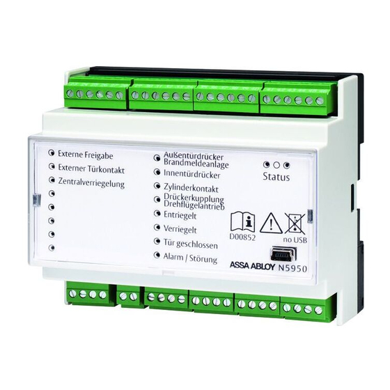
Assa Abloy OneSystem IO-Modul N5950 Manuals
Manuals and User Guides for Assa Abloy OneSystem IO-Modul N5950. We have
1
Assa Abloy OneSystem IO-Modul N5950 manual available for free PDF download: Installation And Mounting Instructions
Assa Abloy OneSystem IO-Modul N5950 Installation And Mounting Instructions (88 pages)
Brand:
Assa Abloy
| Category:
I/O Systems
| Size: 4 MB
Table of Contents
Deutsch
3
Table of Contents
3
Produktinformation
4
Das Onesystem IO-Modul N5950
4
Das Onesystem IO-Modul N5950 Bietet
4
Der Hi-O Technology™-Bus
4
Der Hi-O Technology™-Bus Bietet
4
Hinweise
5
Zu dieser Anleitung
5
Bedeutung der Symbole
5
Sicherheitshinweise
6
Bestimmungsgemäßer Gebrauch
7
Eingänge und Ausgänge
8
Belegung der Ein- und Ausgänge
8
Eingänge
9
Input E1 - Externe Freigabe
9
Input E2 - Externer Türkontakt
9
Input E3 - Zentralverriegelung
9
Input B - Brandmeldeanlage
9
Ausgänge / Relais
10
Relais R1 - Außentürdrücker
10
Relais R1 - Brandmeldeanlage
10
Relais R2 - Innentürdrücker Betätig
10
Relais R3 - Schließzylinder Betätigt
10
Relais R4 - Türdrückerkupplung
10
Relais R4 - Drehflügelantrieb
10
Relais R5 - Entriegelt
10
Relais R6 - Verriegelt
10
Relais R7 - Tür Geschlossen
10
Statusmeldungen / Leds
11
Produkte in Hi-O-Gruppen Organisieren
11
Konfigurationen
12
Gehäuse Öffnen
12
Die Platine
12
Drehschalter - Konfigurieren der
13
Externen Freigabe
13
Position 0 - Direktmodus
13
Position 1 bis E - Zeitmodus
13
Position F - Togglemodus für Dauerfreigabe
13
DIP-Schalter
14
DIP-Schalter 1 - Einstellung der
14
Hi-O-Gruppe
14
DIP-Schalter 2 - Abschlusswiderstand
14
Zuschalten (Terminieren)
14
DIP-Schalter 3 - Disable Plug & Play
14
DIP-Schalter 4 - Schlosstyp
15
DIP-Schalter 5 - ohne Funktion
15
DIP-Schalter 6 - ohne Funktion
15
DIP-Schalter 7 - Überwachung der
15
Brandmeldeanlage
15
Jumper
15
Montage
16
Montieren / Demontieren
16
Elektrischer Anschluss
17
Spannungsversorgung
17
Kennzeichnung der Kabel
17
Anschlussbeispiele
18
Einflügelige Paniktür mit Überwachung
18
Zweiflügelige Paniktür mit Überwachung - eine Hi-O-Gruppe
19
Zweiflügelige Paniktür mit Überwachung - Zwei Hi-O-Gruppen
20
Motorschloss IM Betrieb mit
21
Brandmeldeanlage
21
Kupplungsschloss
23
Feuerschutzmodul Anschließen
24
Technische Daten
25
Zubehör, Wartung, Gewährleistung, Entsorgung
26
Zubehör
26
Gewährleistung
26
Entsorgung
26
Problem, Ursache, Lösung
27
Keine Reaktion auf Ansteuersignal
27
LED an Relais 8 Leuchtet nicht
28
Aktualisierte Informationen
28
English
31
Product Information
32
The Onesystem IO Module N59504
32
IO Module N5950 Offers
32
The Hi-O Technology™ Bus Offers
32
Notices
33
About These Instructions
33
Meaning of Symbols
33
Safety Instructions
34
Intended Use
35
Inputs and Outputs
36
Assignment of Inputs and Outputs
36
Inputs
37
Input E1 - External Release
37
Input E2 - External Door Contact
37
Input E3 - Central Locking
37
Input B - Fire Alarm System
37
Outputs / Relays
38
Relay R1 - Outer Door Handle
38
Relay R1 - Fire Alarm System
38
Relay R2 - Inner Door Handle Actuated
38
Relay R3 - Locking Cylinder Actuated
38
Relay R4 - Door Handle Coupling
38
Relay R4 - Swing Door Drive
38
Relay R5 - Unlocked
38
Relay R6 - Unlocked
38
Relay R7 - Door Closed
38
Status Messages / Leds
39
Organise Products in Hi-O Groups
39
Configurations
40
Open Housing
40
Circuit Board
40
Rotary Switch - Configuring the External Release
41
Position 0 - Direct Mode
41
Positions 1 to E - Time Mode
41
Position F - Toggle Mode for Permanent
41
Release
41
DIP Switch
42
DIP Switch 1 - Hi-O Group Setting
42
DIP Switch 2 - Activate Terminating
42
Resistor (Terminate)
42
DIP Switch 3 - Disable Plug & Play
42
DIP Switch 4 - Lock Type
43
DIP Switch 5 - no Function
43
DIP Switch 6 - no Function
43
DIP Switch 7 - Monitoring of the Fire Alarm System
43
Jumper
43
Mounting
44
Mounting / Disassembly
44
Electrical Connection
45
Power Supply
45
Identification of the Cable
45
Connection Examples
46
Single-Leaf Panic Door with Monitoring
46
Double-Leaf Panic Door with Monitoring - One Hi-O Group
47
Double-Leaf Panic Door with Monitoring - Two Hi-O Groups
48
Motorised Lock in Operation with
49
Fire Alarm System
49
Motorised Lock in Operation Without
50
Fire Alarm System
50
Coupling Lock
51
Connect Fire Protection Module
52
Technical Specifications
53
Accessories, Maintenance
54
Warranty, Disposal
54
Accessories
54
Warranty
54
Disposal
54
Problem, Cause, Solution
55
No Reaction to Control Signal
55
LED on Relay 8 Is Not Lit
56
Updated Information
56
Français
59
Informations Sur Le Produit
60
Le Module IO N5950 Onesystem
60
Le Module IO N5950 Onesystem Offre
60
Le Bus Hi-O Technology
60
Le Bus Hi-O Technology™ Offre
60
Avis
61
À Propos de Cette Notice
61
Signification des Pictogrammes
61
Consignes de Sécurité
62
Utilisation Conforme
63
Entrées Et Sorties
64
Affectation des Entrées Et Sorties
64
Entrées
65
Input E1 - Autorisation Externe
65
Input E2 - Contact de Porte Externe
65
Input E3 - Verrouillage Central
65
Input B - Système de Détection D'incendie
65
Sorties / Relais
66
Relais R1 - Béquille Extérieure
66
Relais R1 - Système de Détection D'incendie
66
Relais R2 - Béquille Intérieure Actionnée
66
Relais R3 - Cylindre de Fermeture Actionné
66
Relais R4 - Coupleur de Béquille
66
Relais R4 - Entraînement de Battant Rotatif
66
Relais R5 - Déverrouillé
66
Relais R6 - Verrouillé
66
Relais R7 - Porte Fermée
66
Signalisations D'état / LED
67
Organiser Les Produits Dans des
67
Groupes Hi-O
67
Configurations
68
Ouvrir Le Boîtier
68
La Platine
68
Commutateur Rotatif - Configuration
69
De L'autorisation Externe
69
Position 0 - Mode Direct
69
Position 1 À E - Mode Horaire
69
Position F - Mode Toggle Pour Autorisation
69
Permanente
69
Commutateur DIP
70
Commutateur DIP 1 - Réglage du
70
Groupe Hi-O
70
Commutateur DIP 2 - Connexion de la
70
Résistance Terminale (Terminer)
70
Commutateur DIP 3 - Désactiver Plug & Play
70
Commutateur DIP 4 - Type de Serrure
71
Commutateur DIP 5 - Sans Fonction
71
Commutateur DIP 6 - Sans Fonction
71
Commutateur DIP 7 - Surveillance du
71
Système de Détection D'incendie
71
Commutateur DIP 8 - Sans Fonction
71
Cavalier
71
Montage
72
Montage / Démontage
72
Raccordement Électrique
73
Tension D'alimentation
73
Identification des Câbles
73
Exemples de Connexion
74
Porte Anti-Panique À un Seul Vantail
74
Avec Surveillance
74
Porte Anti-Panique À Deux Vantaux Avec Surveillance - un Groupe Hi-O
75
Porte Anti-Panique À Deux Vantaux Avec Surveillance - Deux Groupes Hi-O
76
Serrure Motorisée en Service Avec Système de Détection D'incendie
77
Serrure Motorisée en Service Sans Système de Détection D'incendie
78
Serrure À Accouplement
79
Raccorder Le Module de Protection
80
Anti-Incendie
80
Caractéristiques Techniques
81
Accessoires, Entretien, Garantie, Élimination
82
Accessoires
82
Garantie
82
Élimination
82
Problème, Cause, Solution
83
Pas de Réaction Au Signal de Commande
83
LED Au Relais 8 N'est Pas Allumée
84
Informations Actualisées
84
Advertisement
Advertisement
Related Products
Assa Abloy N5951000PILL000
Assa Abloy N59990000000000
Assa Abloy OneSystem N5952
Assa Abloy CLIQ N532
Assa Abloy CLIQ N551
Assa Abloy CLIQ N531
Assa Abloy CLIQ N534
Assa Abloy N59FS
Assa Abloy Norton 6021 Series
Assa Abloy Yale NTM642-NN-ZW3
Assa Abloy Categories
Door locks
Door Opening System
Locks
Security System
Keypad
More Assa Abloy Manuals
Login
Sign In
OR
Sign in with Facebook
Sign in with Google
Upload manual
Upload from disk
Upload from URL