Table of Contents
Advertisement
Quick Links
IS31LT3948 MR16 DEMO Board Guide
IS31LT3948 is a PFM step-up DC-DC converter
designed for driving the white LED arrays for large size
LCD panel backlighting applications. With internal OVP
circuit, the chip and the system can be safe even if the
load is not connected. The device features external
PWM dimming or DC dimming, which allows the
flexible control of the backlighting luminance.
IS31LT3948 incorporates a unique FB scheme which
automatically adjusts the integrated DC/DC converter
to the optimum output voltage for the system,
maximizing the efficiency.
IS31LT3948 general DEMO board is used in general
lamp.
Wide input voltage range: 5V-100V
Constant Current Output limited only by external
Component Selection (Note)
No loop compensation required
Internal over-voltage protection
Internal over-temperature protection
Note: The maximum output current is determined by Vout/Vin
ratio as well as the external components. If output current and
Vout/Vin ratio is high, high current components of inductor
and NMOS are needed.
Part Number
IS31LT3948-GRLS2-EBMR16
30VDC Power supply
LED panel (1W LED, 7 LEDs in series)
Multi-meter
Recommended Input and Output Ratings
No.
Name
1
AL Capacitor
2
AL Capacitor
3
SMD Capacitor
4
SMD Resistor
5
SMD Resistor
6
SMD Resistor
7
SMD Resistor
8
SMD Resistor
9
SMD Resistor
10
Schottky Diode
11
Diode
12
SMD Inductor
Integrated Silicon Solution, Inc. – www.issi.com
R1.0, 18/12/2012
Description
Features
Order information
Package Type
SOP-8
Quick Start
Recommended Equipment
Description
470uF±10%,35V
220uF±10%,50V,Low ESR
10uF±10%,50V
2.4KΩ±1%,1206
24KΩ±1%,0805
270KΩ±1%,0805
10KΩ±1%,0805
0.21Ω±1%,0805
0.9Ω±1%,0805
SS36,3A,60V,SMA
1N4007,1A,1000V,SMA
100uH,Isat≥3A
Input: 10-17VDC
Output: 7LEDs in series/333mA
Note: The input voltage must be lower than the output
voltage(total Vf).
Input voltage ≤ 35VDC
Output voltage≤ 28VDC
Caution: Do not exceed the conditions listed above, otherwise
the board will be damaged or the output current will be
limited.
The IS31LT3948 DEMO Board is fully assembled and
tested. Follow the steps listed below to verify board
operation.
Caution: Do not turn on the power supply until all connections
are completed.
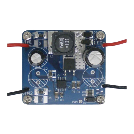
1)
Connect the negative terminal of the power supply
to the VIN1 pin and the positive terminal to the
VIN2 pin.
2)
Connect the negative of the LED panel (LED
arrays) to the LED- terminal.
3)
Connect the positive of the LED panel (LED arrays)
to the LED+ terminal.
4)
Turn on the power supply and the LED panel (LED
arrays) will be light.
Ref Des.
Qty.
C1
1
C3
1
C4
1
R1
1
R4
1
R3
1
R7
1
R5
1
R8
1
D1-D5
5
Ds
1
L1
1
Absolute Maximum Ratings
Procedure
Bill of Materials
Mfr
1
Advertisement
Table of Contents

Subscribe to Our Youtube Channel
Related Manuals for ISSI IS31LT3948


Summary of Contents for ISSI IS31LT3948
- Page 1 DC/DC converter to the optimum output voltage for the system, Procedure maximizing the efficiency. The IS31LT3948 DEMO Board is fully assembled and IS31LT3948 general DEMO board is used in general tested. Follow the steps listed below to verify board lamp.
- Page 2 IS31LT3948 MR16 DEMO Board Guide 3A,60V,AP2310,SOT-23,NMOS IS31LT3948,SOP8 Figure 1 IS31LT3948 MR16 DEMO Board Schematic IS31LT3948 ground connection should be as short Detailed Description and wide as possible to have an accurate LED current. Component Selection • The capacitor C1, C2, C3 should be placed as close The component selection is very important.
- Page 3 Copyright © 2006 integrated Silicon Solution, Inc. All rights reserved. ISSI reserves the right to make changes to this specification and its products at any time without notice. ISSI assumes no liability arising out of the application or use of any information, products or services described herein.
Need help?
Do you have a question about the IS31LT3948 and is the answer not in the manual?
Questions and answers