Advertisement
AM5K COMBINED DEPTH/TENSION
CONTENTS
1.0
2.0
3.0
4.0
5.0
6.0
7.0
AM5KA Measure Head
MEASUREMENT DEVICE
BAKER ATLAS
AM5KA509 (CH - one encoder)
AM5KA517 (OH - Zone 2)
AM5KA518 (OH - two encoders)
6.1
6.2
Magnetic Mark Detector and Cable
6.3
Load Pin and Cable
6.4
Encoder and Cables
6.5
RevL
Sep 2007
Page 1 of 50
Advertisement
Table of Contents

Related Manuals for Benchmark BAKER ATLAS AM5K Series


Summary of Contents for Benchmark BAKER ATLAS AM5K Series
-
Page 1: Table Of Contents
AM5K COMBINED DEPTH/TENSION MEASUREMENT DEVICE BAKER ATLAS AM5KA509 (CH – one encoder) AM5KA517 (OH - Zone 2) AM5KA518 (OH – two encoders) CONTENTS GENERAL SYSTEM DESCRIPTION OPERATION MAINTENANCE AND REPAIR RECOMMENDED SPARE PARTS DRAWINGS AND PARTS LISTS Measure Head Assembly Magnetic Mark Detector and Cable Load Pin and Cable Encoder and Cables... -
Page 2: General
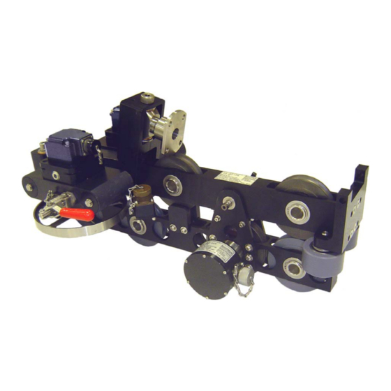
1.0 GENERAL The AM5K Wireline Measuring Device is a compact and lightweight device for measuring both wireline depth and tension. The device is designed to be mounted to the spooling arm of a wireline unit. It is unique to other measuring devices in that it measures both depth and tension on wireline cables from .190”... -
Page 3: System Description
2.0 SYSTEM DESCRIPTION DEPTH MEASUREMENT: The AM5K Measuring Head uses dual spring-loaded measuring wheels to measure the amount of wireline moving to and from the borehole. The measuring wheels are coupled to one or two optical encoders that transmit electrical signals via a cable to the hoistman’s panel and/or logging computer. -
Page 4: Operation
OPERATION SPOOLING ARM INSTALLATION – OVERHEAD SPOOLING ARM Install the measuring head on to the spooling arm by using the top adapter mount assembly to mount to an overhead spooling arm. The mount is designed to mount with a standard U-joint yoke. MOUNTING YOKE AM5KA Measure Head RevL... - Page 5 Make sure that the head can freely sit on the wireline. If the mounting arrangement will not let the head travel up and down freely and if the cable puts a upward or downward force on the measuring head, this force will cause an offset to the tension measurement which will result in an incorrect tension reading.
- Page 6 SPOOLING ARM INSTALLATION – ASEP SPOOLING ARM Use this mount if the measuring head is to be installed on a unit with an ASEP Autospooler. The mount is installed on the horizontal bar. The head is pinned to the mount and can be easily removed by removing the pins. Parent Item Number: AM5KA243 KIT MOUNTING AM5K ASEP OH ARM Component...
- Page 7 AM3KP058 SCREW 10-24 X 1-1/4 SHCS SST AM5KP040 SCREW 10-24 X 3/8 SOC HD SST AMS1P065 NUT 1/2-13 HEX SST AM3KP059 NUT 10-24 ELASTIC STOP SST AMS1P047 WASHER 5/16 LOCK SS C276P036 WASHER 1/4 LOCK SS ACMU2P31 WASHER 1/4 FLAT 5/8OD SST AMS1P054 WASHER #10 FLAT SS C276P035...
- Page 8 CABLE INSTALLATION To install cable, first open the wheels by shifting the red release handles. Next, remove the push pin, and hinge the head open. Lifting up on the wireline cable makes it easier to remove the push pin. The cable can now be inserted or removed. Close the red release handles to tighten the wheels against the wireline.
- Page 9 CABLE REMOVAL UNDER LOAD 3.4.1 If under load, the load will need to be removed from the device prior to removing the retaining pin. A “C-clamp" or a nylon "ratchet strap" can be used to remove the load. 3.4.2 Install a C-Clamp across the top and bottom frames as shown in the drawing below.
- Page 10 CHANGING CONFIGURATION BETWEEN OPEN HOLE AND CASED HOLE A measuring head configured for open hole will typically contain a magnetic mark detector and a 2 encoder. Cased hole operations rarely require a magnetic mark detector and typically use only one encoder. If the head is configured for open hole, no changes are required to run it on a cased hole unit.
- Page 11 3.6.2 To install the deep grooved tension wheel, a modified load pin is available that is calibrated to so the K factor of 1 be used. 3.6.3 The deep grooved tension wheel can be used with a standard load pin. If it is, the Load Cell K factor must be changed to compensate for the reduced bend angle of the cable (refer to 3.6.1) 3.6.4 The Load Pin and grooved tension wheel can be ordered from Kerr...
- Page 12 SYSTEM OPERATION Determine cable size to be used – .490" to .190” Since the wireline cable actually bends around the tension wheel, the bend radius of the wireline cable will affect the tension measurement. These corrections are automatically made in the 5762XA Kerr Hoistman's panel by selecting the proper cable size using the menu.
-
Page 13: Maintenance And Repair
MAINTENANCE AND REPAIR PRE-JOB CHECK Each time the system is used perform the following steps: Verify that the AM5K is properly and securely attached to the spooling arm. Several different mounting kits are available for different types of spooling arms. Verify that the depth measuring wheels are clean and that no groove has been worn into the measuring wheel surface. - Page 14 MONTHLY MAINTENANCE Visually inspect the interiors of the electrical connectors for the encoders and electronic load axle for dirt and evidence of insulation breakdown. Clean or replace as necessary. Install dust caps on the connectors if the cables are removed. Manually rotate each wheel by hand to verify its condition.
- Page 15 AM5KA Measure Head RevL Sep 2007 Page 15 of 50...
- Page 16 ASSEMBLY / DISASSEMBLY PROCEDURES 4.4.1 MEASURING WHEEL, SHAFT, AND BEARING REMOVAL Either measuring wheel can be removed from the measuring head. First shift the red release handle to move the wheel away from the frame. Next remove the encoder with its adapter. On the later model heads, the wheels (item 22) are keyed onto the shaft and can be removed simply by removing the screw holding the wheel to the shaft (item 85).
- Page 17 4.4.3 ELECTRONIC LOAD PIN REMOVAL The electronic load pin is held in place by one retaining ring on the outer end of its shaft. Remove the retaining ring. The load pin can then be removed from the mounting frame. 4.4.4 BACKUP DEPTH MAGNETIC PICKUP REMOVAL AND INSTALLATION The backup depth magnetic pickup is mounted to the encoder adapter.
- Page 18 Use a screw driver to capture the end of the spring (see photo). The end cap and the pin can now be removed (see Photo) AM5KA Measure Head RevL Sep 2007 Page 18 of 50...
- Page 19 Use a hook to pull the spring out far enough to remove the screwdriver (Careful not to bend the spring). Remove the floating encoder assembly. Repeat for the other side. Remove anti-rotation screw (if equipped). Remove snap ring and pull out sliding shaft. Remove the wheel assembly.
- Page 20 Insert a 3/16” x 1/2” long roll pin into the hole. Do not use a longer roll pin as it will put the wheel into a bind. AM5KA Measure Head RevL Sep 2007 Page 20 of 50...
- Page 21 AM5KA Measure Head RevL Sep 2007 Page 21 of 50...
- Page 22 Drive the roll pin flush. Make sure that the wheel can freely slide up and down. Remove the bolt and install the load pin. AFTER ASSEMBLY IS COMPLETE THE HEAD SHOULD BE CONFIGURED AS SHOWN BELOW AM5KA Measure Head RevL Sep 2007 Page 22 of 50...
-
Page 23: Recommended Spare Parts
RECOMMENDED SPARE PARTS It is recommended that the following list of parts be kept on hand for remote locations. ITEM PART NUM DESCRIPTION AM5KA069 ASSY LOAD AXLE 1.5V DIFF EEx REPLACES AMTKA010 AM5KA070 ENCODER HD2.5D-0-SS-37F-512/780 EEx REPLACES AM5KP163 AM5KA055 ASSY ENCODER BACKUP MAGNETIC OPTION AM5KM001 WHEEL MEASURING 2FT 5 SPOKE... -
Page 24: Drawings And Parts Lists
DRAWINGS AND PARTS LISTS MEASURE HEAD ASSEMBLY SIDE VIEW AM5KA Measure Head RevL Sep 2007 Page 24 of 50... - Page 25 TOP VIEW AM5KA Measure Head RevL Sep 2007 Page 25 of 50...
- Page 26 FRONT VIEW AM5KA Measure Head RevL Sep 2007 Page 26 of 50...
- Page 27 REAR VIEW AM5KA Measure Head RevL Sep 2007 Page 27 of 50...
- Page 28 PARTS LIST ITEM PART NUM DESCRIPTION AM5KA131 ASSY FRAME BACKBONE UPPER 5WHL AM5KA232 ASSY FRAME BKBN LWR 5WHL GII AM5KA052-1 ASSY MOUNT FLTNG ENCDR WHL W/ OPTION W/MAG BACKUP AM5KA052-2 ASSY MOUNT FLTNG ENCDR WHL W/0 AM5KA053 ASSY BLOCK PIVOT HORIZ/VERT AM5KM057 ADAPTER ENCODER H37C/H25D OPTION...
- Page 29 AM5KM040 PUSHROD TOGGLE CLAMP PLASTIC AMS1P009 RETAINING PIN (T HANDLE) AMS1P072 PLUG 3/8 NPT SS AM5KP075 CHAIN SASH #35 SST AM5KM157 BEARING BALL 35MM ID MOD AM5KP088 BEARING LINEAR 30MMID X 40MMOD C276P002 BEARING BALL 20MM FAFNIR 204PP AM5KM134 BEARING BALL 40MM ID MOD AM5KP001 CLAMP TOGGLE PUSH/PULL SST AM5KM055...
- Page 30 AMS1P014 O-RING 2-152 BUNA N ENC ADPTR AM5KP071 O-RING 2-141 BUNA N H25 ENCDR AM5KP119 O-RING 2-026 BUNA N MMD CONN C276P042 O-RING 2-016 BUNA N BACKUP CONN AM5KP130 NOZZLE GREASE FITTNG FLUSH NOT SHOWN AM5KA Measure Head RevL Sep 2007 Page 30 of 50...
- Page 31 MAGNETIC MARK DETECTOR SPECIFICATION 1. General This specification describes the latest Kerr Measurement Systems magnetic mark detector. The pc board is potted to prevent damage from shock, vibration, or humidity. 2. Power Input power is 9 - 30vdc at 100ma max. 3.
- Page 32 MAGNETIC MARK DETECTOR SPECIFICATION (continued) AM5KA066 ASSY MMD FLAT HOUSING EEx AM5KM029 ENCLSR MAGNETIC MARK DETECTOR AM5KM035 COVER MAGNETIC MARK DETECTOR ACMU1P21 CONN MS3102E-20-27P 14 PIN RECEPT AM5KP119 O-RING 2-026 BUNA N MMD CONN 1-1/4 X 1-3/8 X 1/16 ACMU1P22 DUST CAP MS25D43-20DA AM5KP072 O-RING 2-046 BUNA N MMD COVER 4.239ID X 4.3790D X 0.070...
- Page 33 MAGNETIC MARK DETECTOR SPECIFICATION (continued) MARK DETECTOR CABLE AMS4A103 – FOCUS ACMU2P21 CONN MS3106E-20-27S AM5KP107 CONN KPT06J16-26P AM5KP093 CABLE 20/8 -40 DEG RATED ACMU2P24 DUST CAP 25042-20DA AM5KA Measure Head RevL Sep 2007 Page 33 of 50...
- Page 34 MAGNETIC MARK DETECTOR SPECIFICATION (continued) MARK DETECTOR CABLE AM5KA041 – ECLIPS AMS4P245 CABLE 20/8 ALPHA 45294 – 40 DEGREE RATED ACMU2P21 CONN MS3106E-20-27S ACMU2P24 DUST CAP MS24042-20DA AM5KP147 CONN KPT06J14-5S AM5KP076 DUST CAP KPT8014C To be able to run the Kerr measuring head on ECLIPS, a small modification will need to be made to the unit.
- Page 35 LOAD PIN AM5KA069 ASSY LOAD AXLE 1.5 V DIFFERENTIAL EEx 45 AMS8P055 CONN KPT 02A16-8P 1 EA 46 AMS8P056 DUST CAP KPT81-16C 1 EA 93 C276P040 O-RING 2-235 BUNA N L/P LID 3-1/8 X 3-3/8 X 1/8 1 EA 94 AMS8P066 O-RING 2-136 BUNA N L/P HSG 1.98ID X 2.19OD X 0.103W 1 EA 95 AM5KP118...
- Page 36 6.3 LOAD PIN (continued) LOAD PIN CABLE AMS8A023 AMS8P057 CONN KPT06A16-8S STR PLUG LOAD PIN END AMS8P058 CONN KPT06A16-8P STR PLUG UNIT END AMS4P245 CABLE 20/8 ALPHA -40 DEGREE RATED AMS7P060 DUST CAP SHELL SIZE 16 AM5KA Measure Head RevL Sep 2007 Page 36 of 50...
- Page 37 AM5KA070 256 PPF / 1280 PPM ENCODER EEx AM5KP163 ENCODER H25D-SS-512/780-ABC-4469 ACMU2P09 DUST CAP MS3181-14C Specifications 512 or 780 Pulses per revolution (dual disc) 5 vdc power Differential Quadrature output (A – A not, B – B not) AM5KP163 ENCODER H25D-SS-512/780-ABC-4469 1 EA AM5KM073 COUPLING MOD ENCDR 0.250/0.375 BORE 1 EA...
- Page 38 Encoder Cable Drawing AMS8A027 AMS1P034 CONN KPT06A14-15S ENCODER AMS4P245 CABLE 20/8 ALPHA 45294 -40 DEGREE RATED AMS1P032 CONN KPT06A14-15P AM5KA Measure Head RevL Sep 2007 Page 38 of 50...
-
Page 39: Backup Odometer
BACKUP ODOMETER CABLE AND WIRING 14 AM5KA055 ASSY ENCODER BACKUP MAGNETIC 1 EA 49 AM5KP027 CONN KPT02E10-6P RECEPTACLE MS3112 1 EA 50 AM5KP034 DUST CAP KPT8110C CANNON SHELL SIZE 10 1 EA 51 AM5KP078 GASKET MS3112 SHELL SIZE 10 NEOPRENE 2 EA 74 AMS1P040 SCREW 6-32 X 3/8 PAN HD SST... -
Page 40: Certification Documentation
CERTIFICATION DOCUMENTATION 7.1 MEASURING HEAD 7.1.1 ATEX Conformity Certificate AM5KA Measure Head RevL Sep 2007 Page 40 of 50... - Page 41 7.1.2 ATEX Conformity Schedule AM5KA Measure Head RevL Sep 2007 Page 41 of 50...
- Page 42 ENCODER 7.2.1 ATEX Conformity Certificate AM5KA Measure Head RevL Sep 2007 Page 42 of 50...
- Page 43 7.2.2 ATEX Conformity Schedule AM5KA Measure Head RevL Sep 2007 Page 43 of 50...
- Page 44 7.2.3 AM5KA070 HI RESOLUTION ENCODER SPECIFICATIONS 512/780 Pulses per revolution – Dual Resolution 5 – 15 vdc power Differential Quadrature output (A – A not, B – B not) Pin Out + 5v Select Case AM5KA Measure Head RevL Sep 2007 Page 44 of 50...
- Page 45 7.3 LOAD PIN 7.3.1 ATEX Conformity Certificate AM5KA Measure Head RevL Sep 2007 Page 45 of 50...
- Page 46 7.3.2 ATEX Conformity Schedule 5.3.3 AM5KA Measure Head RevL Sep 2007 Page 46 of 50...
- Page 47 7.3.3 TENSION SPECIFICATIONS Power Requirements: +/-15 vdc power Kerr proprietary circuit board which amplifies the load pin signals and provides a 1.5v differential output. 0vdc = 0lbs, 1.5vdc = 20,000 lbs. Temperature stability: <= .015% full scale / deg F on zero <= .02% full scale / deg F on output Accuracy:...
- Page 48 7.4 MAGNETIC MARK DETECTOR 7.4.1 ATEX Conformity Certificate AM5KA Measure Head RevL Sep 2007 Page 48 of 50...
- Page 49 7.4.2 ATEX Conformity Schedule AM5KA Measure Head RevL Sep 2007 Page 49 of 50...
- Page 50 7.4.3 MAGNETIC MARK DETECTOR SPECIFICATIONS Input Power 9 - 30vdc at 100ma max. Digital line driver out for strong & strong\ and also weak & weak\ A strong mark is greater than 4.1 gauss measured 0.10 inch from cable surface. A weak mark is 4 gauss or less or'd with a strong mark so either a weak mark or strong mark will provided a signal on the weak mark output.
Need help?
Do you have a question about the BAKER ATLAS AM5K Series and is the answer not in the manual?
Questions and answers