Huawei AR Series Hardware Installation And Maintenance Manual
Industrial switch routers
Hide thumbs
Also See for AR Series:
- Quick start manual (12 pages) ,
- Quick maintenance manual (16 pages)

Related Manuals for Huawei AR Series


Summary of Contents for Huawei AR Series
- Page 1 Huawei AR500&AR530&AR550 series Industrial Switch Routers Hardware Installation and Maintenance Guide Issue Date 2015-12-01 HUAWEI TECHNOLOGIES CO., LTD.
- Page 2 Notice The purchased products, services and features are stipulated by the contract made between Huawei and the customer. All or part of the products, services and features described in this document may not be within the purchase scope or the usage scope. Unless otherwise specified in the contract, all statements, information, and recommendations in this document are provided "AS IS"...
- Page 3 NOTICE is used to address practices not related to personal injury. Issue 05 (2015-12-01) Huawei Proprietary and Confidential Copyright © Huawei Technologies Co., Ltd.
- Page 4 2.3 Checking the Cabinet Updates in Issue 03 (2015-04-10) This issue has the following updates: The following section is added: 3 Installing an AR500 Series Industrial Access Router Issue 05 (2015-12-01) Huawei Proprietary and Confidential Copyright © Huawei Technologies Co., Ltd.
- Page 5 Hardware Installation and Maintenance Guide Issue 02 (2015-01-31) This issue has the following updates: The following section is modified: 5.6.6 Connecting 2-pin DC Power Cables Issue 01 (2014-11-30) Initial official release. Issue 05 (2015-12-01) Huawei Proprietary and Confidential Copyright © Huawei Technologies Co., Ltd.
- Page 6 4.4 Scenario 4: Installing the Router in a Cabinet (Using a 550 Horizontal Rack-Mounting Kit)........52 4.5 Scenario 5: Mounting the Router in a Cabinet (Using a Mounting Kit)..............58 4.6 Installing SIM Cards..............................62 Issue 05 (2015-12-01) Huawei Proprietary and Confidential Copyright © Huawei Technologies Co., Ltd.
- Page 7 6.3.1 Environmental Requirements for an Equipment Room..................177 6.3.2 Requirements for Power Supply..........................185 6.4 Appendix D Equipment Grounding Specifications....................188 6.4.1 General Grounding Specifications...........................188 6.4.2 Grounding Specifications for an Equipment Room....................188 Issue 05 (2015-12-01) Huawei Proprietary and Confidential Copyright © Huawei Technologies Co., Ltd.
- Page 8 6.5.4 Engineering Labels for User Cables........................203 6.5.5 Engineering Labels for Power Cables........................204 6.6 Appendix F Guide to Using Optical Modules......................207 6.7 Appendix G Fault Tag..............................210 Issue 05 (2015-12-01) Huawei Proprietary and Confidential Copyright © Huawei Technologies Co., Ltd.
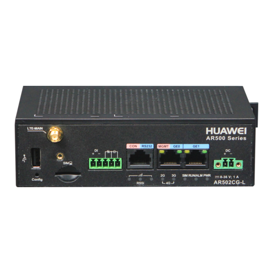
- Page 9 Figures in the document are for reference only and may not show the actual appearance of the equipment. Figure 1-1 shows appearances of the AR series routers. Issue 05 (2015-12-01) Huawei Proprietary and Confidential Copyright © Huawei Technologies Co., Ltd.
- Page 10 Huawei AR500&AR530&AR550 series Industrial Switch Routers 1 Introduction to the Industrial Routers Hardware Installation and Maintenance Guide Figure 1-1 Appearances of the AR series routers AR502G-L-D-H AR531-F2C-H FE 7 FE 6 e Sur viva l Pow er Ou tag MO NIT OR...
- Page 11 About This Chapter 2.1 Reading Carefully the Safety Cautions 2.2 Checking the Installation Site 2.3 Checking the Cabinet 2.4 Checking the Power Supply System 2.5 Preparing Installation Tools Issue 05 (2015-12-01) Huawei Proprietary and Confidential Copyright © Huawei Technologies Co., Ltd.
- Page 12 NOTICE, CAUTION, and DANGER items in this document do not cover all the safety cautions and are only supplementary to the safety cautions. Only trained and qualified personnel are allowed to install or maintain Huawei equipment. Familiarize yourself with all safety cautions before performing any operation on the equipment.
- Page 13 Before installing the equipment, ensure that the environment in the installation site meet equipment operation requirements. Heat Dissipation There must be more than 100 mm clearance around the equipment for heat dissipation. Issue 05 (2015-12-01) Huawei Proprietary and Confidential Copyright © Huawei Technologies Co., Ltd.
- Page 14 "Water projected by a nozzle against enclosure from any direction shall have no harmful effects." Corrosive Gases Avoidance There must be no acidic, alkaline, or other corrosive gases in the installation site. Issue 05 (2015-12-01) Huawei Proprietary and Confidential Copyright © Huawei Technologies Co., Ltd.
- Page 15 Table 2-2 Power supply requirements Item Requirement Preparation The power supply system must be ready before the router installation. Issue 05 (2015-12-01) Huawei Proprietary and Confidential Copyright © Huawei Technologies Co., Ltd.
- Page 16 – Maximum voltage range: 9.6 V to 60 2.5 Preparing Installation Tools Table 2-3 lists the installation tools required for router installation. Table 2-3 Installation tools Tool Function Picture Measuring Measures distances. tape Issue 05 (2015-12-01) Huawei Proprietary and Confidential Copyright © Huawei Technologies Co., Ltd.
- Page 17 Crimping Crimps network tool cables. Network Tests network cable cable tester connectivity and helps locate network faults. Issue 05 (2015-12-01) Huawei Proprietary and Confidential Copyright © Huawei Technologies Co., Ltd.
- Page 18 Ladder Enables operators to work at heights. Combinatio Loosens and fastens n wrench nuts. Vacuum Absorbs dusts. cleaner Level Checks whether a plane is horizontal. Issue 05 (2015-12-01) Huawei Proprietary and Confidential Copyright © Huawei Technologies Co., Ltd.
- Page 19 3.4 Scenario 4: Installing the Router in a Meter Box 3.5 Installing a SIM Card 3.6 (Optional) Installing Antennas 3.7 Connecting the Router 3.8 Powering On and Off the Router Issue 05 (2015-12-01) Huawei Proprietary and Confidential Copyright © Huawei Technologies Co., Ltd.
- Page 20 Step 1 Attach four rubber pads in the imprinted round areas marked plus (+) signs at the bottom of the router. Step 2 Gently place the router on the desk. Issue 05 (2015-12-01) Huawei Proprietary and Confidential Copyright © Huawei Technologies Co., Ltd.
- Page 21 Install the router at an appropriate height to ensure that the indicators can be observed easily. Tools and Accessories Measuring tape Marker Phillips screwdriver Mounting bracket M3x6 countersunk screws (four) M4x8 pan head screws (two) Issue 05 (2015-12-01) Huawei Proprietary and Confidential Copyright © Huawei Technologies Co., Ltd.
- Page 22 Use the Phillips screwdriver to install two M4x8 pan head screws in the marked positions on the wall, and leave 2 mm of the screws out of the wall. Issue 05 (2015-12-01) Huawei Proprietary and Confidential Copyright © Huawei Technologies Co., Ltd.
- Page 23 Make sure the following prerequisites are met before the installation: The DIN rail has been secured in position. The router is placed near the DIN rail for convenient movement. Issue 05 (2015-12-01) Huawei Proprietary and Confidential Copyright © Huawei Technologies Co., Ltd.
- Page 24 Step 4 Make the router incline forward with the bottom away from the DIN rail, and place the fixture at the rear of the DIN mounting kit on the top of the DIN rail. Issue 05 (2015-12-01) Huawei Proprietary and Confidential Copyright © Huawei Technologies Co., Ltd.
- Page 25 To avoid electric shock, do not connect power cables while the power is on. Make sure the following prerequisites are met before the installation: The DIN rail has been secured in position. Issue 05 (2015-12-01) Huawei Proprietary and Confidential Copyright © Huawei Technologies Co., Ltd.
- Page 26 Step 3 Use the Phillips screwdriver to loosen the screws on the left fixture on the DIN rail in the meter box, and then move the fixture to leave appropriate clearance for the router. Issue 05 (2015-12-01) Huawei Proprietary and Confidential Copyright © Huawei Technologies Co., Ltd.
- Page 27 If the spring latch is too tight to move down, you can pull down the spring latch during the installation. Step 7 Move the left fixture to attach it to the router, and then use the Phillips screwdriver to tighten the screws on the fixture. Issue 05 (2015-12-01) Huawei Proprietary and Confidential Copyright © Huawei Technologies Co., Ltd.
- Page 28 A router must use Huawei-certified SIM cards. Non-Huawei-certified SIM cards cannot ensure reliability and may affect service stability. Huawei is not responsible for any problem caused by the use of non-Huawei-certified SIM cards and will not fix such problems.
- Page 29 If only one SIM card needs to be installed, install it in slot SIM1. Step 3 Install the SIM card cover back to the router and tighten the screw to fix the cover. ----End 3.6 (Optional) Installing Antennas Issue 05 (2015-12-01) Huawei Proprietary and Confidential Copyright © Huawei Technologies Co., Ltd.
- Page 30 Step 2 Adjust positions of the antennas to obtain the optimal wireless transmission and receiving performance. If the router is placed on a desk, make the primary antenna vertical to the desk and the secondary antenna parallel to the desk. Issue 05 (2015-12-01) Huawei Proprietary and Confidential Copyright © Huawei Technologies Co., Ltd.
- Page 31 Hardware Installation and Maintenance Guide If the router is mounted on a wall, make the primary antenna parallel to the wall and the secondary antenna vertical to the wall. Issue 05 (2015-12-01) Huawei Proprietary and Confidential Copyright © Huawei Technologies Co., Ltd.
- Page 32 Do not power on the router before you finish connecting cables. l Notice flags on interfaces when connecting cables. Incorrect cable connections may damage interface modules or the router. Issue 05 (2015-12-01) Huawei Proprietary and Confidential Copyright © Huawei Technologies Co., Ltd.
- Page 33 Do not power on the router before you finish connecting cables. l Notice flags on interfaces when connecting cables. Incorrect cable connections may damage interface modules or the router. Issue 05 (2015-12-01) Huawei Proprietary and Confidential Copyright © Huawei Technologies Co., Ltd.
- Page 34 Step 2 Fix the outdoor LTE antenna on the fixture (delivered with the antenna), and then mount the antenna and fixture on the pole, as shown in Figure 3-1. Figure 3-1 Mounting the antenna on the pole Issue 05 (2015-12-01) Huawei Proprietary and Confidential Copyright © Huawei Technologies Co., Ltd.
- Page 35 The console cable is not included in the installation accessory package and needs to be purchased separately. Procedure Step 1 Connect the console cable. Connect a DB9 connector of the console cable to the RS232 interface (DB9) of the router. Issue 05 (2015-12-01) Huawei Proprietary and Confidential Copyright © Huawei Technologies Co., Ltd.
- Page 36 Ethernet cables (separately purchased) Labels for Ethernet cables (self-prepared) Procedure Step 1 Select Ethernet cables of appropriate quantity and lengths according to the number of interfaces and measured cabling distances. Issue 05 (2015-12-01) Huawei Proprietary and Confidential Copyright © Huawei Technologies Co., Ltd.
- Page 37 The ground cable of a router must be correctly connected to protect the router against lightning and interference. l Do not power on the router before you finish connecting cables. Issue 05 (2015-12-01) Huawei Proprietary and Confidential Copyright © Huawei Technologies Co., Ltd.
- Page 38 Use a multimeter to measure the resistance between the ground points at two ends of the ground cable. The resistance must be smaller than 5 ohm. 3.7.4 Connecting RS485/RS422 Cables Issue 05 (2015-12-01) Huawei Proprietary and Confidential Copyright © Huawei Technologies Co., Ltd.
- Page 39 Do not cut the metal conductor of the cable when peeling insulation coating. Insert the bare wire into a wire hole. Tighten the screw on the wire hole with a flat-head screwdriver to lock the cable. Issue 05 (2015-12-01) Huawei Proprietary and Confidential Copyright © Huawei Technologies Co., Ltd.
- Page 40 Connect the RS485/RS422 cables at the other end to a meter or monitoring device. Meter or monitoring device ----End 3.7.5 Connecting the Power Cable Issue 05 (2015-12-01) Huawei Proprietary and Confidential Copyright © Huawei Technologies Co., Ltd.
- Page 41 Connect the 4-pin DC connector of the router's power cable to the packet socket on the router and the other end to an external DC power supply system. Issue 05 (2015-12-01) Huawei Proprietary and Confidential Copyright © Huawei Technologies Co., Ltd.
- Page 42 Connect the input terminal of the AC power cable for the 25 W open frame power supply to the power socket on 25 W open frame power supply, and connect the power plug at the other end to an AC power source. Issue 05 (2015-12-01) Huawei Proprietary and Confidential Copyright © Huawei Technologies Co., Ltd.
- Page 43 The DC input voltage is in the range of 8 V to 36 V. Procedure Power on the router. Turn on the power switch of the external power supply system to start the router. Issue 05 (2015-12-01) Huawei Proprietary and Confidential Copyright © Huawei Technologies Co., Ltd.
- Page 44 ----End Follow-up Procedure After the router starts, you can log in to its CLI to configure, manage, and maintain the router. For details, see the CLI-based Configuration. Issue 05 (2015-12-01) Huawei Proprietary and Confidential Copyright © Huawei Technologies Co., Ltd.
- Page 45 4.5 Scenario 5: Mounting the Router in a Cabinet (Using a Mounting Kit) 4.6 Installing SIM Cards 4.7 (Optional) Installing Antennas 4.8 Connecting the Router 4.9 Powering On and Off the Router Issue 05 (2015-12-01) Huawei Proprietary and Confidential Copyright © Huawei Technologies Co., Ltd.
- Page 46 M4x30 screws (two) Combination wrench (10 mm) Phillips screwdriver Procedure Step 1 Screw lock nuts on the hex bolts and fix the hex bolts on the mounting bracket. Issue 05 (2015-12-01) Huawei Proprietary and Confidential Copyright © Huawei Technologies Co., Ltd.
- Page 47 Step 3 Use a combination wrench to screw the two hex bolts on the mounting bracket. When the DIN rail is fixed with the raised hex bolts, tighten the lock nuts by rotating the wrench counterclockwise. Issue 05 (2015-12-01) Huawei Proprietary and Confidential Copyright © Huawei Technologies Co., Ltd.
- Page 48 Step 4 Align an M4x20 screw with the topmost tapped hole on the mounting bracket, and screw it about 5 mm into the tapped hole with a Phillips screwdriver. Step 5 Use two M4x20 screws to fix the stainless steel sheet on the router. Issue 05 (2015-12-01) Huawei Proprietary and Confidential Copyright © Huawei Technologies Co., Ltd.
- Page 49 Step 6 Loosen the screws on the front top cover with the Phillips screwdriver, remove the front top cover, and keep it in an appropriate place for later use. Issue 05 (2015-12-01) Huawei Proprietary and Confidential Copyright © Huawei Technologies Co., Ltd.
- Page 50 Use two M4x30 screws to fix the router onto the mounting bracket and tighten the topmost screw on the mounting bracket. Issue 05 (2015-12-01) Huawei Proprietary and Confidential Copyright © Huawei Technologies Co., Ltd.
- Page 51 Ensure that there are no flammable or explosive materials near the router and no obstructions within 100 mm around the router. l Install the router at an appropriate height to ensure that the indicators can be observed easily. Issue 05 (2015-12-01) Huawei Proprietary and Confidential Copyright © Huawei Technologies Co., Ltd.
- Page 52 Step 1 Attach the mounting bracket against the wall and adjust its position to keep the top and bottom edges horizontal. Mark positions of the four mounting holes with a marker. 120mm Issue 05 (2015-12-01) Huawei Proprietary and Confidential Copyright © Huawei Technologies Co., Ltd.
- Page 53 Step 3 Align an M4x20 screw with the topmost tapped hole on the mounting bracket, and screw it about 5 mm into the tapped hole with a Phillips screwdriver. Step 4 Use two M4x20 screws to fix the stainless steel sheet on the router. Issue 05 (2015-12-01) Huawei Proprietary and Confidential Copyright © Huawei Technologies Co., Ltd.
- Page 54 Step 5 Loosen the screws on the front top cover with the Phillips screwdriver, remove the front top cover, and keep it in an appropriate place for later use. Issue 05 (2015-12-01) Huawei Proprietary and Confidential Copyright © Huawei Technologies Co., Ltd.
- Page 55 Use two M4x30 screws to fix the router onto the mounting bracket and tighten the topmost screw on the mounting bracket. Issue 05 (2015-12-01) Huawei Proprietary and Confidential Copyright © Huawei Technologies Co., Ltd.
- Page 56 Make sure the following prerequisites are met before the installation: Issue 05 (2015-12-01) Huawei Proprietary and Confidential Copyright © Huawei Technologies Co., Ltd.
- Page 57 The 530 horizontal rack-mounting kit, floating nuts, M4 screws, and M6 screws are not included in the installation accessory package and needs to be purchased separately. Procedure Step 1 Use two M4x20 screws to fix the stainless steel sheet on the router. Issue 05 (2015-12-01) Huawei Proprietary and Confidential Copyright © Huawei Technologies Co., Ltd.
- Page 58 Step 2 Loosen the screws on the front top cover with a Phillips screwdriver, remove the front top cover, and keep it in an appropriate place for later use. Issue 05 (2015-12-01) Huawei Proprietary and Confidential Copyright © Huawei Technologies Co., Ltd.
- Page 59 Step 4 Install two floating nuts on each front mounting rail of the cabinet. Leave four mounting holes between the two floating nuts on the same mounting rail. Issue 05 (2015-12-01) Huawei Proprietary and Confidential Copyright © Huawei Technologies Co., Ltd.
- Page 60 Use the Phillips screwdriver to tighten the lower M6 screws and then the upper M6 screws. ----End 4.4 Scenario 4: Installing the Router in a Cabinet (Using a 550 Horizontal Rack-Mounting Kit) Issue 05 (2015-12-01) Huawei Proprietary and Confidential Copyright © Huawei Technologies Co., Ltd.
- Page 61 The length of six adjacent mounting holes may not be 2 U. Observe the scale ticks on the mounting rails when installing floating nuts. l You can use a flat-head screwdriver to install floating nuts. Issue 05 (2015-12-01) Huawei Proprietary and Confidential Copyright © Huawei Technologies Co., Ltd.
- Page 62 M6 screws and then the upper ones to fix the rack-mounting kit. Step 3 Screw lock nuts on the hex bolts and fix the hex bolts on the mounting bracket. Issue 05 (2015-12-01) Huawei Proprietary and Confidential Copyright © Huawei Technologies Co., Ltd.
- Page 63 Step 5 Use a combination wrench to screw the hex bolts on the mounting bracket. When the DIN rail is fixed with the raised hex bolts, tighten the lock nuts by rotating the wrench counterclockwise. Issue 05 (2015-12-01) Huawei Proprietary and Confidential Copyright © Huawei Technologies Co., Ltd.
- Page 64 Step 6 Align an M4x20 screw with the topmost tapped hole on the mounting bracket, and screw it about 5 mm into the tapped hole with the Phillips screwdriver. Step 7 Use two M4x20 screws to fix the stainless steel sheet on the router. Issue 05 (2015-12-01) Huawei Proprietary and Confidential Copyright © Huawei Technologies Co., Ltd.
- Page 65 Step 8 Loosen the screws on the front top cover with the Phillips screwdriver, remove the front top cover, and keep it in an appropriate place for later use. Issue 05 (2015-12-01) Huawei Proprietary and Confidential Copyright © Huawei Technologies Co., Ltd.
- Page 66 AR 530 Se ries INFR ARE AR53 1-F2C RUN /ALM RS4 85-0 RS4 85-1 ----End 4.5 Scenario 5: Mounting the Router in a Cabinet (Using a Mounting Kit) Issue 05 (2015-12-01) Huawei Proprietary and Confidential Copyright © Huawei Technologies Co., Ltd.
- Page 67 MO NIT OR G E1 G E0 DI- 1 DI- 0 RS 48 5-1 RS 48 5-0 C O N SO FE 5 FE 4 FE 3 FE 2 Issue 05 (2015-12-01) Huawei Proprietary and Confidential Copyright © Huawei Technologies Co., Ltd.
- Page 68 Step 3 Align the mounting holes on the lower part of the router with the tapped holes on the mounting kit, and secure the router on the mounting kit with two M4x30 screws. Issue 05 (2015-12-01) Huawei Proprietary and Confidential Copyright © Huawei Technologies Co., Ltd.
- Page 69 P W R R U N /A LM R S 48 5- R S 48 5- Step 4 Use M4 screws to secure the mounting kit in the cabinet. Issue 05 (2015-12-01) Huawei Proprietary and Confidential Copyright © Huawei Technologies Co., Ltd.
- Page 70 A router must use Huawei-certified SIM cards. Non-Huawei-certified SIM cards cannot ensure reliability and may affect service stability. Huawei is not responsible for any problem caused by the use of non-Huawei-certified SIM cards and will not fix such problems.
- Page 71 If only one SIM card needs to be installed, install it in slot SIM1 (on the left). Step 3 Install the SIM card cover back to the router and tighten the screw to fix the cover. ----End 4.7 (Optional) Installing Antennas Issue 05 (2015-12-01) Huawei Proprietary and Confidential Copyright © Huawei Technologies Co., Ltd.
- Page 72 Step 1 Connect the antennas to the SMA connectors on the rear panel of the router. Step 2 Place the antennas in appropriate angles to facilitate installation of the cable outlet panel. Issue 05 (2015-12-01) Huawei Proprietary and Confidential Copyright © Huawei Technologies Co., Ltd.
- Page 73 Sub-GHz antenna Self-tapping screw Anti-theft screw Procedure Step 1 Insert the connector of the sub-GHz antenna into the ZigBee/sub-GHz interface on the rear panel of the router. Issue 05 (2015-12-01) Huawei Proprietary and Confidential Copyright © Huawei Technologies Co., Ltd.
- Page 74 Do not power on the router before you finish connecting cables. Tools and Accessories Phillips screwdriver ESD wrist strap Multimeter Ground Cable M6 screw (separately purchased) Issue 05 (2015-12-01) Huawei Proprietary and Confidential Copyright © Huawei Technologies Co., Ltd.
- Page 75 Use a multimeter to measure the resistance between the ground points at two ends of the ground cable. The resistance must be smaller than 5 ohm. 4.8.2 Connecting the Console Cable Issue 05 (2015-12-01) Huawei Proprietary and Confidential Copyright © Huawei Technologies Co., Ltd.
- Page 76 Connect the DB9 connector of the console cable to the serial interface (COM) of a management PC. CONSOLE CONSOLE Power outage Survival MONITOR RESERVE RS485-0 RS485-1 DI-0 DI-1 COM interface Console cable ----End Issue 05 (2015-12-01) Huawei Proprietary and Confidential Copyright © Huawei Technologies Co., Ltd.
- Page 77 CLI of the router. NOTE The default user name is admin, and the default password is Admin@huawei. For details on how to log in through the console port, see "Logging In to the System for the First Time"...
- Page 78 Step 3 Connect one end of an Ethernet cable to an Ethernet interface of the router and the other end to an Ethernet interface of the remote device. Issue 05 (2015-12-01) Huawei Proprietary and Confidential Copyright © Huawei Technologies Co., Ltd.
- Page 79 Check the following items after connecting Ethernet cables: Labels are correctly filled and securely attached to cables, with texts facing the same direction. Cables and connectors are complete, intact, and tightly connected. Issue 05 (2015-12-01) Huawei Proprietary and Confidential Copyright © Huawei Technologies Co., Ltd.
- Page 80 Do not cut the metal conductor of the cable when peeling insulation coating. Hold down the white button above a wire hole on the 8-pin terminal block to open the reed. Insert the bare wire into the wire hole. Issue 05 (2015-12-01) Huawei Proprietary and Confidential Copyright © Huawei Technologies Co., Ltd.
- Page 81 Connect the RS485 cables to electric meters or other devices with RS485 interfaces, and connect the DI cables to digital input devices. Issue 05 (2015-12-01) Huawei Proprietary and Confidential Copyright © Huawei Technologies Co., Ltd.
- Page 82 4.8.5 Connecting Optical Modules and Optical Fibers Context CAUTION Invisible laser beams will cause eye damage. Do not look into bores of optical modules or connectors of optical fibers without eye protection. Issue 05 (2015-12-01) Huawei Proprietary and Confidential Copyright © Huawei Technologies Co., Ltd.
- Page 83 NOTICE l Huawei devices must use Huawei-certified optical modules. Non-Huawei-certified optical modules cannot ensure transmission reliability and may affect service stability. Huawei is not responsible for any problem caused by the use of non-Huawei-certified optical modules and will not fix such problems.
- Page 84 Do not power on a router before you finish installing the router and connecting cables. The power cable length must be shorter than or equal to 3 m. Table 4-4 lists the required specifications of the power cables. Issue 05 (2015-12-01) Huawei Proprietary and Confidential Copyright © Huawei Technologies Co., Ltd.
- Page 85 Insert a flat-head screwdriver into the square hole above a wire hole on the 4-pin terminal block and apply force on the screwdriver to open the metal reed. Insert the bare wire into the wire hole. Issue 05 (2015-12-01) Huawei Proprietary and Confidential Copyright © Huawei Technologies Co., Ltd.
- Page 86 Connect the 4-pin terminal block to the AC power socket of the router and push the slide blocks at two sides of the connector, until you hear a click. Connect cables at the other end to an external AC power supply system. Issue 05 (2015-12-01) Huawei Proprietary and Confidential Copyright © Huawei Technologies Co., Ltd.
- Page 87 Do not power on a router before you finish installing the router and connecting cables. The power cable length must be shorter than or equal to 3 m. Table 4-5 lists the required specifications of the power cables. Issue 05 (2015-12-01) Huawei Proprietary and Confidential Copyright © Huawei Technologies Co., Ltd.
- Page 88 Use a wire stripper to peel about 7 mm length of insulation coating off one end of the cable. NOTICE Do not cut the metal conductor of the cable when peeling insulation coating. Insert the bare wire into the wire hole. Issue 05 (2015-12-01) Huawei Proprietary and Confidential Copyright © Huawei Technologies Co., Ltd.
- Page 89 There must be no exposed metal part at the joints of wire holes and bare wires on the 2- pin terminal block. Step 4 Connect the 2-pin DC power cables. Issue 05 (2015-12-01) Huawei Proprietary and Confidential Copyright © Huawei Technologies Co., Ltd.
- Page 90 To avoid electric shock, do not connect power cables while the power is on. NOTICE Do not power on a router before you finish installing the router and connecting cables. Tools and Accessories Wire stripper Flat-head screwdriver Issue 05 (2015-12-01) Huawei Proprietary and Confidential Copyright © Huawei Technologies Co., Ltd.
- Page 91 There must be no exposed metal part at the joints of wire holes and bare wires on the AC input terminal block. Step 4 Connect the AC input power cables. Issue 05 (2015-12-01) Huawei Proprietary and Confidential Copyright © Huawei Technologies Co., Ltd.
- Page 92 Connect a network interface of the router to an input GE interface of the 180 W PoE midspan using a network cable. Connect an output GE interface of the 180 W PoE midspan to the PD using another network cable. Issue 05 (2015-12-01) Huawei Proprietary and Confidential Copyright © Huawei Technologies Co., Ltd.
- Page 93 Step 1 Determine the cable outlets to be used on the cable outlet panel based on the number and positions of cables, and use diagonal pliers to remove the covers from the cable outlets. Issue 05 (2015-12-01) Huawei Proprietary and Confidential Copyright © Huawei Technologies Co., Ltd.
- Page 94 Step 3 Check all the external cables to ensure that they are routed out from the planned outlets. Install the front top cover back to the router, tighten screws on the cover, and cover the screws with plastic caps. Issue 05 (2015-12-01) Huawei Proprietary and Confidential Copyright © Huawei Technologies Co., Ltd.
- Page 95 After the router starts, check indicators on the front panel to check whether the router runs normally. Figure 4-3 describes the indicator states when the router is running normally. Issue 05 (2015-12-01) Huawei Proprietary and Confidential Copyright © Huawei Technologies Co., Ltd.
- Page 96 R S 48 5- Indicator Description Steady green: The system power supply is normal. RUN/ALM Slow blinking green: The system is running properly. Power off the router. Issue 05 (2015-12-01) Huawei Proprietary and Confidential Copyright © Huawei Technologies Co., Ltd.
- Page 97 ----End Follow-up Procedure After the router starts, you can log in to its CLI to configure, manage, and maintain the router. For details, see the CLI-based Configuration. Issue 05 (2015-12-01) Huawei Proprietary and Confidential Copyright © Huawei Technologies Co., Ltd.
- Page 98 5.4 Installing a 180 W PoE Midspan on a DIN Rail 5.5 Installing a 180 W PoE Midspan in a Cabinet 5.6 Connecting the Router 5.7 Powering On and Off the Router Issue 05 (2015-12-01) Huawei Proprietary and Confidential Copyright © Huawei Technologies Co., Ltd.
- Page 99 Step 3 Slowly push the router toward the DIN rail to make the spring latch at the rear of the router move down. The spring latch then bounces back to fix the router on the DIN rail. Issue 05 (2015-12-01) Huawei Proprietary and Confidential Copyright © Huawei Technologies Co., Ltd.
- Page 100 The length of six adjacent mounting holes may not be 2 U. Observe the scale ticks on the mounting rails when installing floating nuts. l You can use a flat-head screwdriver to install floating nuts. Issue 05 (2015-12-01) Huawei Proprietary and Confidential Copyright © Huawei Technologies Co., Ltd.
- Page 101 Step 5 Slowly push the router toward the DIN rail to make the spring latch at the rear of the router move down. The spring latch then bounces back to fix the router on the DIN rail. Issue 05 (2015-12-01) Huawei Proprietary and Confidential Copyright © Huawei Technologies Co., Ltd.
- Page 102 DIN rail 60 W AC power module NOTE The 60 W AC power module is not included in the installation accessory package and needs to be purchased separately. Issue 05 (2015-12-01) Huawei Proprietary and Confidential Copyright © Huawei Technologies Co., Ltd.
- Page 103 Step 5 Slowly push the power module toward the DIN rail to make the spring latch near the bottom of the DIN mounting kit move down. The spring latch then bounces back to fix the power module on the DIN rail. Issue 05 (2015-12-01) Huawei Proprietary and Confidential Copyright © Huawei Technologies Co., Ltd.
- Page 104 The DIN rail has been secured in position. The router is placed near the DIN rail for convenient movement. Tools and Accessories DIN rail 180 W PoE midspan Issue 05 (2015-12-01) Huawei Proprietary and Confidential Copyright © Huawei Technologies Co., Ltd.
- Page 105 PoE midspan move down. The spring latch then bounces back to fix the PoE midspan on the DIN rail. NOTE If the spring latch is too tight to move down, you can pull down the spring latch during the installation. ----End Issue 05 (2015-12-01) Huawei Proprietary and Confidential Copyright © Huawei Technologies Co., Ltd.
- Page 106 The length of six adjacent mounting holes may not be 2 U. Observe the scale ticks on the mounting rails when installing floating nuts. l You can use a flat-head screwdriver to install floating nuts. Issue 05 (2015-12-01) Huawei Proprietary and Confidential Copyright © Huawei Technologies Co., Ltd.
- Page 107 Step 5 Slowly push the PoE midspan toward the DIN rail to make the spring latch at the rear of the PoE midspan move down. The spring latch then bounces back to fix the PoE midspan on the DIN rail. Issue 05 (2015-12-01) Huawei Proprietary and Confidential Copyright © Huawei Technologies Co., Ltd.
- Page 108 Step 1 Wear an ESD wrist strap. Ensure that the ESD wrist strap is grounded and in a close contact with your wrist. Step 2 Connect the ground cable. Issue 05 (2015-12-01) Huawei Proprietary and Confidential Copyright © Huawei Technologies Co., Ltd.
- Page 109 Connect the M6 lug of the ground cable to a ground point on the wall or DIN rail, and secure the M6 lug with an M6 screw. ----End 5.6.2 Connecting the Console Cable Issue 05 (2015-12-01) Huawei Proprietary and Confidential Copyright © Huawei Technologies Co., Ltd.
- Page 110 Connect the RJ45 connector of the console cable to the console interface (RJ45) of the router. Connect the DB9 connector of the console cable to the serial interface (COM) of a management PC. ----End Issue 05 (2015-12-01) Huawei Proprietary and Confidential Copyright © Huawei Technologies Co., Ltd.
- Page 111 CLI of the router. NOTE The default user name is admin, and the default password is Admin@huawei. For details on how to log in through the console port, see "Logging In to the System for the First Time"...
- Page 112 Step 3 Connect one end of an Ethernet cable to an Ethernet interface of the router and the other end to an Ethernet interface of the remote device. Issue 05 (2015-12-01) Huawei Proprietary and Confidential Copyright © Huawei Technologies Co., Ltd.
- Page 113 Labels are correctly filled and securely attached to cables, with texts facing the same direction. Cables and connectors are complete, intact, and tightly connected. 5.6.4 Connecting Optical Modules and Optical Fibers Issue 05 (2015-12-01) Huawei Proprietary and Confidential Copyright © Huawei Technologies Co., Ltd.
- Page 114 NOTICE l Huawei devices must use Huawei-certified optical modules. Non-Huawei-certified optical modules cannot ensure transmission reliability and may affect service stability. Huawei is not responsible for any problem caused by the use of non-Huawei-certified optical modules and will not fix such problems.
- Page 115 Step 6 Replace all the temporary labels with formal labels on the optical fibers. ----End 5.6.5 Connecting Boolean Output Cables Context DANGER To avoid electric shock, do not connect power cables while the power is on. Issue 05 (2015-12-01) Huawei Proprietary and Confidential Copyright © Huawei Technologies Co., Ltd.
- Page 116 Use a wire stripper to peel about 7 mm length of insulation coating off one end of the cable. NOTICE Do not cut the metal conductor of the cable when peeling insulation coating. Insert the bare wire into a wire hole. Issue 05 (2015-12-01) Huawei Proprietary and Confidential Copyright © Huawei Technologies Co., Ltd.
- Page 117 Insert pins of the 3-pin terminal block to the Boolean output interfaces of the router, and then tighten the slotted screws at both ends of the terminal block with a flat-head screwdriver. Connect cables on the other to external digital input devices. Issue 05 (2015-12-01) Huawei Proprietary and Confidential Copyright © Huawei Technologies Co., Ltd.
- Page 118 To avoid electric shock, do not connect power cables while the power is on. NOTICE Do not power on a router before you finish installing the router and connecting cables. Issue 05 (2015-12-01) Huawei Proprietary and Confidential Copyright © Huawei Technologies Co., Ltd.
- Page 119 Use a wire stripper to peel about 7 mm length of insulation coating off one end of the cable. NOTICE Do not cut the metal conductor of the cable when peeling insulation coating. Insert the bare wire into a wire hole. Issue 05 (2015-12-01) Huawei Proprietary and Confidential Copyright © Huawei Technologies Co., Ltd.
- Page 120 There must be no exposed metal part at the joints of wire holes and bare wires on the 2- pin terminal block. Step 4 Connect the 2-pin DC power cables. Issue 05 (2015-12-01) Huawei Proprietary and Confidential Copyright © Huawei Technologies Co., Ltd.
- Page 121 (RTN(+)), neutral wire (NEG(-)), and earth wire. Insert the bare wire into the hole on the terminal block. Then the reed is closed to lock the cable in the hole. Issue 05 (2015-12-01) Huawei Proprietary and Confidential Copyright © Huawei Technologies Co., Ltd.
- Page 122 (-) in the second hole. Insert the bare wire into a hole on the terminal block. Then the reed is closed to lock the cable in the hole. Issue 05 (2015-12-01) Huawei Proprietary and Confidential Copyright © Huawei Technologies Co., Ltd.
- Page 123 Connect cables at the other end to an external power supply system. ----End 5.6.7 Connecting the 180 W PoE Midspan Issue 05 (2015-12-01) Huawei Proprietary and Confidential Copyright © Huawei Technologies Co., Ltd.
- Page 124 Insert the two cables into the 2-pin terminal block, with the RTN (+) cable in the left hole and the NEG (-) cable in the right hole. Issue 05 (2015-12-01) Huawei Proprietary and Confidential Copyright © Huawei Technologies Co., Ltd.
- Page 125 Do not cut the metal conductor of the cable when peeling insulation coating. Insert the bare wire into a wire hole. Tighten the screw on the wire hole with a flat-head screwdriver to lock the cable. Issue 05 (2015-12-01) Huawei Proprietary and Confidential Copyright © Huawei Technologies Co., Ltd.
- Page 126 Connect the 2-pin terminal block at the other end to the 2-pin DC output power socket of the 180 W PoE midspan, and then tighten the slotted screws at both ends of the terminal block with the flat-head screwdriver. Issue 05 (2015-12-01) Huawei Proprietary and Confidential Copyright © Huawei Technologies Co., Ltd.
- Page 127 Insert the three cables into the AC input terminal block from left to right in the sequence of live wire (RTN(+)), neutral wire (NEG(-)), and earth wire. Use a wire stripper to peel about 7 mm length of insulation coating off one end of the cable. Issue 05 (2015-12-01) Huawei Proprietary and Confidential Copyright © Huawei Technologies Co., Ltd.
- Page 128 Connect AC cables at the other end to an external AC power supply system. Issue 05 (2015-12-01) Huawei Proprietary and Confidential Copyright © Huawei Technologies Co., Ltd.
- Page 129 Connect a network interface of the router to an input GE interface of the 180 W PoE midspan using a network cable. Connect an output GE interface of the 180 W PoE midspan to the PD using another network cable. Issue 05 (2015-12-01) Huawei Proprietary and Confidential Copyright © Huawei Technologies Co., Ltd.
- Page 130 After the router starts, check indicators on the front panel to check whether the router runs normally. Figure 5-1 describes the indicator states when the router is running normally. Issue 05 (2015-12-01) Huawei Proprietary and Confidential Copyright © Huawei Technologies Co., Ltd.
- Page 131 Hardware Installation and Maintenance Guide Figure 5-1 Normal indicator states on the router Indicator Description Slow blinking green: The system is running properly. Power off the router. Issue 05 (2015-12-01) Huawei Proprietary and Confidential Copyright © Huawei Technologies Co., Ltd.
- Page 132 ----End Follow-up Procedure After the router starts, you can log in to its CLI to configure, manage, and maintain the router. For details, see the CLI-based Configuration. Issue 05 (2015-12-01) Huawei Proprietary and Confidential Copyright © Huawei Technologies Co., Ltd.
- Page 133 6.3 Appendix C Environmental Requirements for Device Operation 6.4 Appendix D Equipment Grounding Specifications 6.5 Appendix E Engineering Labels for Cables 6.6 Appendix F Guide to Using Optical Modules 6.7 Appendix G Fault Tag Issue 05 (2015-12-01) Huawei Proprietary and Confidential Copyright © Huawei Technologies Co., Ltd.
- Page 134 USB flash drive. After the USB flash drive is removed, the RUN/ALM indicator slow blinks red for 3 seconds, indicating that it enters the system indicator mode. Issue 05 (2015-12-01) Huawei Proprietary and Confidential Copyright © Huawei Technologies Co., Ltd.
- Page 135 Off: The 3G/2G link is not connected and is inactive. Possible causes are: l The 3G/2G module does not work normally. l The 3G/2G module is not connected to a 3G/2G network. Issue 05 (2015-12-01) Huawei Proprietary and Confidential Copyright © Huawei Technologies Co., Ltd.
- Page 136 The ZigBee/sub-GHz module does not work normally. l The ZigBee networking fails to be established or the sub-GHz antenna interface fails to connect to the peer end. Issue 05 (2015-12-01) Huawei Proprietary and Confidential Copyright © Huawei Technologies Co., Ltd.
- Page 137 When a USB flash drive is installed, the RUN indicator is used as the USB indicator. Table 6-9 describes the possible states of the RUN indicator. Issue 05 (2015-12-01) Huawei Proprietary and Confidential Copyright © Huawei Technologies Co., Ltd.
- Page 138 Blinking: The LAN FE interface is transmitting or receiving data. WAN GE Combo Indicator Table 6-11 describes the possible states of a WAN GE combo indicator. Issue 05 (2015-12-01) Huawei Proprietary and Confidential Copyright © Huawei Technologies Co., Ltd.
- Page 139 48 V power supply normally. Off: The PoE power socket does not provide 48 V power supply normally or is not connected to any power source. Issue 05 (2015-12-01) Huawei Proprietary and Confidential Copyright © Huawei Technologies Co., Ltd.
- Page 140 Steady on: The power supply level for PDs is 4. Off: The router is not supplying power to PDs. Signal Indicator Table 6-16 describes the possible states of the signal indicators. Issue 05 (2015-12-01) Huawei Proprietary and Confidential Copyright © Huawei Technologies Co., Ltd.
- Page 141 Fast blinking: The system is powering on or is restarting. Off: The system software is not running or is resetting. PWR Indicator Table 6-19 describes the possible states of the PWR indicator. Issue 05 (2015-12-01) Huawei Proprietary and Confidential Copyright © Huawei Technologies Co., Ltd.
- Page 142 Silkscreen Color Description GE interface Green Steady on: The GE interface is transmitting indicator or receiving data. Off: The GE interface is not transmitting or receiving data. Issue 05 (2015-12-01) Huawei Proprietary and Confidential Copyright © Huawei Technologies Co., Ltd.
- Page 143 Precautions for Assembly Use dedicated tools or tools delivered by Huawei and follow the methods given here during assembly. Hold terminals of cables instead of pulling the cables themselves when installing or removing cable components.
- Page 144 Step 1 Based on the cross-sectional area of the cable conductor, strip a length of insulation coating C to expose the conductor D of length L1, as shown in Figure 6-2. The recommended values of L1 are listed in Table 6-22. Issue 05 (2015-12-01) Huawei Proprietary and Confidential Copyright © Huawei Technologies Co., Ltd.
- Page 145 When you strip a power cable, do not damage the conductor of the cable. l If the bare crimping terminal is not provided by Huawei, the value of L1 is 1 mm (0.04 in.) to 2 mm (0.08 in.) greater than the value of L.
- Page 146 Step 5 Push the heat shrink tubing (A) toward the connector until the tube covers the crimped part, and then use a heat gun to heat the tube, as shown in Figure 6-5. Issue 05 (2015-12-01) Huawei Proprietary and Confidential Copyright © Huawei Technologies Co., Ltd.
- Page 147 Figure 6-6 Components of a JG terminal and a power cable A. JG terminal B. Heat-shrinkable tubing C. Insulation layer of a power D. Conductor of a power cable cable Issue 05 (2015-12-01) Huawei Proprietary and Confidential Copyright © Huawei Technologies Co., Ltd.
- Page 148 NOTICE l When you strip a power cable, do not damage the conductor of the cable. l If the bare crimping terminal is not provided by Huawei, you can adjust the value of L as required. Figure 6-7 Stripping a power cable (JG terminal)
- Page 149 Step 5 Push the heat shrink tubing toward the connector until the tube covers the crimped part, and then use a heat gun to heat the tube, as shown in Figure 6-10. Figure 6-10 Heating the heat shrink tubing (JG terminal) Issue 05 (2015-12-01) Huawei Proprietary and Confidential Copyright © Huawei Technologies Co., Ltd.
- Page 150 6-12. The recommended values of L1 are listed in Table 6-24. NOTICE When you strip a power cable, do not damage the conductor of the cable. Figure 6-12 Stripping a power cable (cord end terminal) Issue 05 (2015-12-01) Huawei Proprietary and Confidential Copyright © Huawei Technologies Co., Ltd.
- Page 151 Figure 6-13 Putting the cord end terminal onto the conductor Step 3 Crimp the joint parts of the cord end terminal and the conductor, as shown in Figure 6-14. Issue 05 (2015-12-01) Huawei Proprietary and Confidential Copyright © Huawei Technologies Co., Ltd.
- Page 152 5.3 (0.21) 16 (0.025) 6 (0.24) 25 (0.039) 8.7 (0.34) 35 (0.054) 10 (0.39) ----End 6.2.3 Assembling Ethernet Cables Assembling the Shielded RJ45 Connector and Ethernet Cable Issue 05 (2015-12-01) Huawei Proprietary and Confidential Copyright © Huawei Technologies Co., Ltd.
- Page 153 Step 2 Remove a 30 mm (1.18 in.) long section of the jacket, cut off the nylon twine inside the jacket, and cut a no more than 5 mm (0.20 in.) cleft in the jacket, as shown in Figure 6-17. Issue 05 (2015-12-01) Huawei Proprietary and Confidential Copyright © Huawei Technologies Co., Ltd.
- Page 154 Along the edge of the metal shell, cut off the aluminum foil shield layer and ensure that there is no surplus copper wire. The exposed twisted-pair cable is about 20 mm (0.79 in.) long, as shown in Figure 6-19. Issue 05 (2015-12-01) Huawei Proprietary and Confidential Copyright © Huawei Technologies Co., Ltd.
- Page 155 Step 6 Align the four pairs of cables in the holder, as shown in Figure 6-22. The connections between the wires and the pins are shown in Figure 6-23 and listed in Table 6-26. Issue 05 (2015-12-01) Huawei Proprietary and Confidential Copyright © Huawei Technologies Co., Ltd.
- Page 156 Table 6-26 Connections between wires and pins (using a straight-through cable as an example) Matching Pins of Wires Wire Color White-Orange Orange White-Green Blue White-Blue Green White-Brown Issue 05 (2015-12-01) Huawei Proprietary and Confidential Copyright © Huawei Technologies Co., Ltd.
- Page 157 Step 9 Push the metal shell toward the connector body until the wire holder and the connector body are engaged completely. Crimp the connector, as shown in Figure 6-26. Issue 05 (2015-12-01) Huawei Proprietary and Confidential Copyright © Huawei Technologies Co., Ltd.
- Page 158 Step 11 To complete the assembly of the other end, repeat Step 1 through Step ----End Assembling an Unshielded RJ45 Connector and Ethernet Cable Context Figure 6-28 shows the components of an unshielded RJ45 connector and cable. Issue 05 (2015-12-01) Huawei Proprietary and Confidential Copyright © Huawei Technologies Co., Ltd.
- Page 159 Table 6-27. Figure 6-30 Connections between wires and pins (unit: mm (in.)) White-Orange Orange White-Green Blue White-Blue Green White-Brown Pin 8 Brown Pin 1 Issue 05 (2015-12-01) Huawei Proprietary and Confidential Copyright © Huawei Technologies Co., Ltd.
- Page 160 Context To ensure proper contact between the crimped wires and the wire conductors, the heights and sizes of the contact strips must be standard and the same. Issue 05 (2015-12-01) Huawei Proprietary and Confidential Copyright © Huawei Technologies Co., Ltd.
- Page 161 NOTE All unqualified pieces must be crimped again. Figure 6-32 Contact strips of different heights Figure 6-33 Contact strips of the same height Issue 05 (2015-12-01) Huawei Proprietary and Confidential Copyright © Huawei Technologies Co., Ltd.
- Page 162 Step 4 Check whether the contact strips and the plastic separators are well aligned and intact. If a separator is skewed and cannot be fixed, replace it with a new RJ45 connector. Figure 6-36 shows an unqualified piece. Figure 6-36 Skewed plastic separators Issue 05 (2015-12-01) Huawei Proprietary and Confidential Copyright © Huawei Technologies Co., Ltd.
- Page 163 Testing the Connection of Assembled Cables Context Huawei provides two types of Ethernet cables: straight-through cables and crossover cables. Straight-through cables are connected in a one-to-one manner. They are used to connect terminals such as a computer or switch to network devices.
- Page 164 Turn the switch to the S position to slow down lighting of the indicators so that you can see the indicators more clearly, as shown in Figure 6-39. Issue 05 (2015-12-01) Huawei Proprietary and Confidential Copyright © Huawei Technologies Co., Ltd.
- Page 165 (right) section of the tester, the indicators turn on in the sequence of 3-6-1-4-5-2-7-8-G. If the indicators do not come on in this sequence, the Ethernet cable is unqualified. Issue 05 (2015-12-01) Huawei Proprietary and Confidential Copyright © Huawei Technologies Co., Ltd.
- Page 166 For example, in this document, the adapters of cable connectors have separate interfaces. In the actual situation, the adapters may have interfaces fixed on equipment. Use dedicated tools provided or specified by Huawei and follow the installation procedure described here.
- Page 167 Sharp objects must not touch cable wiring to prevent damage to cables. To protect power cables, route power cables of the active and standby power modules separately. Installing Power Adapters Installing the OT Terminal Issue 05 (2015-12-01) Huawei Proprietary and Confidential Copyright © Huawei Technologies Co., Ltd.
- Page 168 Figure 6-43 Installing an OT terminal, showing the orientation of crimping sleeve Place the spring washer and flat washer in turn, mount a matching screw, and fasten it clockwise, as shown in Figure 6-44. Issue 05 (2015-12-01) Huawei Proprietary and Confidential Copyright © Huawei Technologies Co., Ltd.
- Page 169 – Bend the upper OT terminal at a 45- or 90-degree angle, as shown in Figure 6-46. – Cross the two terminals, as shown in Figure 6-47. Issue 05 (2015-12-01) Huawei Proprietary and Confidential Copyright © Huawei Technologies Co., Ltd.
- Page 170 Step 1 Hold a cord end terminal upright and place it on a terminal jack, as shown in Figure 6-48. To ensure bump contact and dense connection, place the plain side of the terminal outwards. Issue 05 (2015-12-01) Huawei Proprietary and Confidential Copyright © Huawei Technologies Co., Ltd.
- Page 171 Step 3 Move the cable slightly and ensure that it is securely connected. Step 4 Before you remove a cord end terminal, loosen the screw counterclockwise. ----End Installing Ethernet Adapters Issue 05 (2015-12-01) Huawei Proprietary and Confidential Copyright © Huawei Technologies Co., Ltd.
- Page 172 Pull the connector slightly and ensure that it is securely connected, as shown in Figure 6-52. Issue 05 (2015-12-01) Huawei Proprietary and Confidential Copyright © Huawei Technologies Co., Ltd.
- Page 173 Installing an Unshielded Ethernet Connector Procedure Step 1 Hold the male and female connectors, with the male connector facing the female connector, as shown in Figure 6-54. Issue 05 (2015-12-01) Huawei Proprietary and Confidential Copyright © Huawei Technologies Co., Ltd.
- Page 174 Step 3 A crisp click indicates that the connector is locked by the locking key. Pull the connector slightly and ensure that it is securely connected. Figure 6-56 shows an installed Ethernet connector. Figure 6-56 Installed unshielded Ethernet connector Issue 05 (2015-12-01) Huawei Proprietary and Confidential Copyright © Huawei Technologies Co., Ltd.
- Page 175 Step 2 Clean the pins again by using dust-free cotton. If necessary, clean the pins by using an air gun. Ensure that the pins are free from any fiber or debris. ----End Installing an FC Fiber Connector Issue 05 (2015-12-01) Huawei Proprietary and Confidential Copyright © Huawei Technologies Co., Ltd.
- Page 176 Figure 6-59 Feeding the male connector into the female connector Step 4 Fasten the locking nut clockwise and ensure that the connector is securely installed, as shown Figure 6-60. Issue 05 (2015-12-01) Huawei Proprietary and Confidential Copyright © Huawei Technologies Co., Ltd.
- Page 177 Step 1 Remove the dustproof cap of the LC fiber connector and store it for future use. Step 2 Align the core pin of the male connector with that of the female connector, as shown in Figure 6-62. Issue 05 (2015-12-01) Huawei Proprietary and Confidential Copyright © Huawei Technologies Co., Ltd.
- Page 178 Figure 6-63 Feeding the male connector into the female connector Step 4 A clicking sound indicates that the male connector is locked, as shown in Figure 6-64. Figure 6-64 Installed LC connector Issue 05 (2015-12-01) Huawei Proprietary and Confidential Copyright © Huawei Technologies Co., Ltd.
- Page 179 (not the pigtail). When you hear a click, the fiber connector is secured by the clips (internal parts, not illustrated in the figure). Pull the fiber connector gently. If the connector does not loosen, the installation is complete. See Figure 6-67. Issue 05 (2015-12-01) Huawei Proprietary and Confidential Copyright © Huawei Technologies Co., Ltd.
- Page 180 Step 1 Remove the dustproof cap of the MPO fiber connector and store it for future use. Step 2 Align the core pin of the male connector with that of the female connector, as shown in Figure 6-69. Issue 05 (2015-12-01) Huawei Proprietary and Confidential Copyright © Huawei Technologies Co., Ltd.
- Page 181 Figure 6-70 Installed MPO fiber connector Step 4 To disassemble an MPO fiber connector, hold the shell labeled "PULL" and remove the male connector, as shown in Figure 6-71. Issue 05 (2015-12-01) Huawei Proprietary and Confidential Copyright © Huawei Technologies Co., Ltd.
- Page 182 Step 2 Hold the handles of the COAX crimping tools to open the self-locking mechanism. The jaw of the COAX crimping tools opens automatically, as shown in Figure 6-73. Issue 05 (2015-12-01) Huawei Proprietary and Confidential Copyright © Huawei Technologies Co., Ltd.
- Page 183 Figure 6-74 Removing the mold from the COAX crimping tools Step 4 Place the mold to be installed into the jaw of the COAX crimping tools and align the screw holes, as shown in Figure 6-75. Issue 05 (2015-12-01) Huawei Proprietary and Confidential Copyright © Huawei Technologies Co., Ltd.
- Page 184 Step 6 Hold the handles of the COAX crimping tools with one hand. Tighten the two fastening screws clockwise. Figure 6-77 Figure 6-78shows the mold installed in the COAX crimping tool. Issue 05 (2015-12-01) Huawei Proprietary and Confidential Copyright © Huawei Technologies Co., Ltd.
- Page 185 The equipment room should also follow local regulations concerning the industrial construction, environmental protection, fire safety, Issue 05 (2015-12-01) Huawei Proprietary and Confidential Copyright © Huawei Technologies Co., Ltd.
- Page 186 Do not use decorative materials that contain sulfur in the equipment room. Equipment Room Layout An equipment room usually contains mobile switching equipment, telecommunications equipment, power supply equipment, and other auxiliary equipment. To ensure easy Issue 05 (2015-12-01) Huawei Proprietary and Confidential Copyright © Huawei Technologies Co., Ltd.
- Page 187 1.0 x 10⁷ ohms to 1.0 x 10¹⁰ ohms. Ground this floor material or raised floor. You can connect them to ground using a one megohm current-limiting resistor and connection line. Issue 05 (2015-12-01) Huawei Proprietary and Confidential Copyright © Huawei Technologies Co., Ltd.
- Page 188 Other Avoid the proliferation of mildew, and keep out rodents (like mice). requirements Figure 6-80 Internal partition wall inside the equipment room Issue 05 (2015-12-01) Huawei Proprietary and Confidential Copyright © Huawei Technologies Co., Ltd.
- Page 189 6-33 lists the requirements for the corrosive gas concentration. Table 6-33 Requirements for corrosive gas concentration Chemical active material Unit Concentration ≤0.20 mg/m ≤0.006 mg/m ≤0.05 mg/m Issue 05 (2015-12-01) Huawei Proprietary and Confidential Copyright © Huawei Technologies Co., Ltd.
- Page 190 Keep the equipment far away from high-power radio transmitters, radar units, and high- frequency and high-current equipment. Use electromagnetic shielding if necessary. Requirements for Lightning Proof Grounding Table 6-34 lists the requirements for lightning proof grounding. Issue 05 (2015-12-01) Huawei Proprietary and Confidential Copyright © Huawei Technologies Co., Ltd.
- Page 191 Do not install a fuse or switch on the ground cable. l All ground cables should be as short as possible, and arranged in a straight line. Issue 05 (2015-12-01) Huawei Proprietary and Confidential Copyright © Huawei Technologies Co., Ltd.
- Page 192 Use the galvanized flat steel with cross-sectional area of 40 mm x 4 mm (1.58 in. x 0.158 in.) or 50 mm x 5 mm (1.97 in. x 0.197 in.). Issue 05 (2015-12-01) Huawei Proprietary and Confidential Copyright © Huawei Technologies Co., Ltd.
- Page 193 For power distribution capacity in the equipment room, both the working current and fault current of the devices should be considered. Ensure that independent AC power supplies Issue 05 (2015-12-01) Huawei Proprietary and Confidential Copyright © Huawei Technologies Co., Ltd.
- Page 194 UPS can rely on concatenation or parallel connection. When an inverter or a UPS is used, the active inverter is determined by the maximum power and a backup inverter is required. Issue 05 (2015-12-01) Huawei Proprietary and Confidential Copyright © Huawei Technologies Co., Ltd.
- Page 195 Use distributed power supply mode. Use multiple DC power supply systems and put power equipment in multiple locations. Adopt a standard DC power supply system, and set the output voltage to the communications equipment within the required range. Issue 05 (2015-12-01) Huawei Proprietary and Confidential Copyright © Huawei Technologies Co., Ltd.
- Page 196 The grounding resistance in an area where the earth resistance rate is high should be less than 10 ohms. 6.4.3 Grounding Specifications for Devices Table 6-38 lists the equipment grounding specifications. Issue 05 (2015-12-01) Huawei Proprietary and Confidential Copyright © Huawei Technologies Co., Ltd.
- Page 197 If the power supply and the equipment are in the same equipment room, use the same protective ground bar for them if possible. Issue 05 (2015-12-01) Huawei Proprietary and Confidential Copyright © Huawei Technologies Co., Ltd.
- Page 198 Table 6-41 Specifications for laying out ground cables Description The grounding wire should not run parallel to or twist around the signal cable. Issue 05 (2015-12-01) Huawei Proprietary and Confidential Copyright © Huawei Technologies Co., Ltd.
- Page 199 Color: chalk white Material: polyester (PET) Ambient temperature: -29°C (-20.2°F) to +149°C (300.2°F) Printed by a laser printer and written with a marker Pass UL and CSA authentication Issue 05 (2015-12-01) Huawei Proprietary and Confidential Copyright © Huawei Technologies Co., Ltd.
- Page 200 The identification plate has an embossed area 0.2 mm x 0.6 mm (0.008 in. x 0.02 in.) around (symmetric on both sides), and the area in the middle is for affixing the label, as shown in Figure 6-82. Issue 05 (2015-12-01) Huawei Proprietary and Confidential Copyright © Huawei Technologies Co., Ltd.
- Page 201 Template for Printing You can obtain a template from the Huawei local office to print labels. The template is made in Microsoft Word. Follow these instructions to use the template: You can modify the contents of the template. Do not change settings of centered characters, direction, and fonts.
- Page 202 After the page setup has been made correctly, save it for future use. This page setup is only necessary the first time you use the template to print the labels. Issue 05 (2015-12-01) Huawei Proprietary and Confidential Copyright © Huawei Technologies Co., Ltd.
- Page 203 Table 6-42 Standard typeface for handwriting Determine the size of characters based on the number of letters or digits and ensure that the characters are distinct and tidy. Issue 05 (2015-12-01) Huawei Proprietary and Confidential Copyright © Huawei Technologies Co., Ltd.
- Page 204 – The identification card should be downward when you lay out the cable horizontally. Figure 6-85 Text area of the label Procedure for attaching labels Figure 6-86 shows the methods and procedures for attaching labels. Issue 05 (2015-12-01) Huawei Proprietary and Confidential Copyright © Huawei Technologies Co., Ltd.
- Page 205 The identification card is to the right of the cable in vertical cabling. The identification card is on the top of the cable in horizontal cabling. Make sure that the label is facing out. Issue 05 (2015-12-01) Huawei Proprietary and Confidential Copyright © Huawei Technologies Co., Ltd.
- Page 206 The side with "TO:" that is facing outside carries the location information of the opposite end; and the other side carries the location information of the local end. Issue 05 (2015-12-01) Huawei Proprietary and Confidential Copyright © Huawei Technologies Co., Ltd.
- Page 207 C: physical slot Numbered in top-down and left-right order starting number from 01. For example, 01 is the first slot at the top left of the chassis. Issue 05 (2015-12-01) Huawei Proprietary and Confidential Copyright © Huawei Technologies Co., Ltd.
- Page 208 Table 6-44 Information on labels affixed to a fiber between a device and an ODF Content Meaning Example MN-B-C-D- MN: cabinet For example, A01. number B: chassis Numbered in bottom-up order with two digits, for number example, 01. Issue 05 (2015-12-01) Huawei Proprietary and Confidential Copyright © Huawei Technologies Co., Ltd.
- Page 209 Example of the Label Figure 6-90 shows a sample label on an optical fiber. Figure 6-90 Sample label on an optical fiber between the device and the ODF Issue 05 (2015-12-01) Huawei Proprietary and Confidential Copyright © Huawei Technologies Co., Ltd.
- Page 210 The contents of the labels for network cables connecting hubs and devices or agents and the network cables for other purposes should be specified according to actual connections. The details are as follows: Issue 05 (2015-12-01) Huawei Proprietary and Confidential Copyright © Huawei Technologies Co., Ltd.
- Page 211 Table 6-46 Contents of the engineering labels for user cables Content Meaning Example MN-B-C-D MN: cabinet For example, A01 is the first cabinet in row A. number Issue 05 (2015-12-01) Huawei Proprietary and Confidential Copyright © Huawei Technologies Co., Ltd.
- Page 212 "MDF-G01-01-01" indicates that the opposite end of the user cable is connected to the terminal in row 01, column 01 of the MDF in row G, column 01 in the equipment room. 6.5.5 Engineering Labels for Power Cables Issue 05 (2015-12-01) Huawei Proprietary and Confidential Copyright © Huawei Technologies Co., Ltd.
- Page 213 For details, see Figure 6-93. Figure 6-93 Example of the labels for DC power cables Issue 05 (2015-12-01) Huawei Proprietary and Confidential Copyright © Huawei Technologies Co., Ltd.
- Page 214 The label only carries location information about the opposite equipment and the power socket; information about the local end is unnecessary. Issue 05 (2015-12-01) Huawei Proprietary and Confidential Copyright © Huawei Technologies Co., Ltd.
- Page 215 (APD). Then the optical module is burnt. The preceding faults lead to temporary or long-term cut-off of optical signals; or even cause permanent damages to the optical module, affecting communication services. Issue 05 (2015-12-01) Huawei Proprietary and Confidential Copyright © Huawei Technologies Co., Ltd.
- Page 216 Issue 05 (2015-12-01) Huawei Proprietary and Confidential Copyright © Huawei Technologies Co., Ltd.
- Page 217 Clean a receptacle with a cotton swab, as shown in Figure 6-100. Clean an optical connector with cleaning tissues. Issue 05 (2015-12-01) Huawei Proprietary and Confidential Copyright © Huawei Technologies Co., Ltd.
- Page 218 For example, optical signals will be lost. 6.7 Appendix G Fault Tag *Customer name: Address: Contact person: Tel.: Fax: Issue 05 (2015-12-01) Huawei Proprietary and Confidential Copyright © Huawei Technologies Co., Ltd.
- Page 219 One Fault Tag should be adapted in one return category, such as RMA/Return/Analysis. l The items marked with "*" are the mandatory fields that you must fill in. Issue 05 (2015-12-01) Huawei Proprietary and Confidential Copyright © Huawei Technologies Co., Ltd.
Need help?
Do you have a question about the AR Series and is the answer not in the manual?
Questions and answers