Advertisement
Quick Links
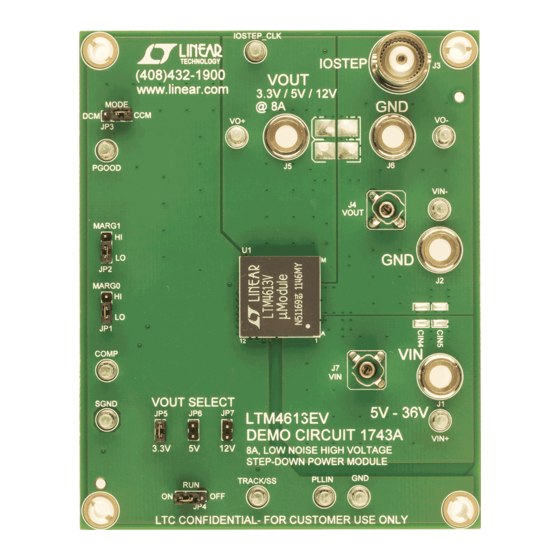
Description
Demonstration circuit DC1743A features the LTM
an EN55022 class B certified, high input and output voltage,
high efficiency, switch mode step-down power µModule
regulator. The input voltage range is from 5V to 36V. The
output voltage is jumper programmable from 3.3V to 12V
with a rated load current of 8A. Derating is necessary
for certain V
, V
, frequency and thermal conditions:
IN
OUT
please refer to LTM4613 data sheet for derating curves.
Only input and output capacitors are needed externally.
The DC1743A offers the TRACK/SS pin allowing the user
to program output tracking or soft-start period. Output
perForMAnce sUMMArY
PARAMETER
Input Voltage Range
Output Voltage V
OUT
Maximum Continuous Output Current
Default Operating Frequency
Efficiency
Load Transient
BoArD photo
DEMO MANUAL DC1743A
4613EV,
voltage margining can also be realized through jumper
®
position selections.
®
Higher efficiency at low load currents is achieved by setting
the MODE pin jumper to DCM. The PLL pin is available
to synchronize the LTM4613EV to an external clock. The
LTM4613 data sheet must be read in conjunction with
this demo manual prior to working on or modifying demo
circuit DC1743A.
Design files for this circuit board are available at
http://www.linear.com/demo
L, LT, LTC, LTM, µModule, Linear Technology and the Linear logo are registered trademarks of
Linear Technology Corporation. All other trademarks are the property of their respective owners.
(T
= 25°C)
A
CONDITIONS
Jumper Selectable
Derating Is Necessary for Certain Operating Conditions. See Data Sheet
for Details.
V
= 12V
OUT
V
= 5V
OUT
V
= 3.3V
OUT
V
= 12V, V
= 5V, I
= 8A
IN
OUT
OUT
V
= 12V, V
= 5V
IN
OUT
8A, High Voltage Power
µModule Regulator
LTM4613
VALUE
5V to 36V
3.3V, 5V, 12V; ± 2%
8A
DC
600kHz
250kHz
165kHz
93.0% See Figure 3
See Figure 4
dc1743af
1
Advertisement

Related Manuals for Linear Technology LTM4613


Summary of Contents for Linear Technology LTM4613
- Page 1 The DC1743A offers the TRACK/SS pin allowing the user http://www.linear.com/demo to program output tracking or soft-start period. Output L, LT, LTC, LTM, µModule, Linear Technology and the Linear logo are registered trademarks of Linear Technology Corporation. All other trademarks are the property of their respective owners. perForMAnce sUMMArY = 25°C)
-
Page 2: Quick Start Procedure
DEMO MANUAL DC1743A qUick stArt proceDUre Demonstration circuit DC1743A is an easy way to evalu- 4. Vary the input voltage from 5V to 36V and adjust the ate the performance of the LTM4613EV. Please refer to load current from 0A to 8A. Observe the output voltage Figure 1 for proper measurement equipment setup and regulation, ripple voltage, efficiency, and other param- follow the procedure below:... - Page 3 DEMO MANUAL DC1743A qUick stArt proceDUre – LOAD – – – – DC1743A F01 Figure 1. Proper Measurement Equipment Setup dc1743af...
- Page 4 DEMO MANUAL DC1743A qUick stArt proceDUre SCOPE PROBE DC1743A F02 Figure 2. Measuring V or V Ripple Efficiency vs Load Current Efficiency vs Load Current Efficiency vs Load Current = 12V) = 24V) = 36V) = 3.3V = 3.3V = 3.3V = 5V = 5V = 5V...
- Page 5 0A TO 4A LOAD STEP 0A TO 4A LOAD STEP = 1x47µF/16V/POSCAP+3x47µF/16V/X5R+1x10µF/16V/X5R = 1x47µF/16V/POSCAP+3x47µF/16V/X5R+1x10µF/16V/X5R Figure 4. Measured Load Transient Responses DC1743A F05 = 24V = 12V = 8A LOAD AMBIENT TEMPERATURE = 23.3°C NO FORCED AIR FLOW Figure 5. Thermal Image of LTM4613 dc1743af...
-
Page 6: Parts List
RES, CHIP 392k 0.06W 1% 0603 VISHAY CRCW0603392KFKEA ZENER DIODE, 5.1V SOT23 ON SEMICONDUCTOR MMBZ5231B I.C., VOLTAGE REG LINEAR TECHNOLOGY CORPORATION LTM4613EV Additional Demo Board Circuit Components MOSFET, N-CHANNEL 30V VISHAY SILICONIX SUD50N03-09 CAP, X7R 1µF 16V 10% 0603 TDK C1608X7R1C105K... -
Page 7: Schematic Diagram
Information furnished by Linear Technology Corporation is believed to be accurate and reliable. However, no responsibility is assumed for its use. Linear Technology Corporation makes no representa- tion that the interconnection of its circuits as described herein will not infringe on existing patent rights. - Page 8 Linear Technology Corporation (LTC) provides the enclosed product(s) under the following AS IS conditions: This demonstration board (DEMO BOARD) kit being sold or provided by Linear Technology is intended for use for ENGINEERING DEVELOPMENT OR EVALUATION PURPOSES ONLY and is not provided by LTC for commercial use. As such, the DEMO BOARD herein may not be complete in terms of required design-, marketing-, and/or manufacturing-related protective considerations, including but not limited to product safety measures typically found in finished commercial goods.
- Page 9 Mouser Electronics Authorized Distributor Click to View Pricing, Inventory, Delivery & Lifecycle Information: Analog Devices Inc. DC1743A...
Need help?
Do you have a question about the LTM4613 and is the answer not in the manual?
Questions and answers