Advertisement
Quick Links
DESCRIPTION
Demonstration circuit 1811B-B is a dual-output, high
efficiency, high density, µModule
26.5V input range. Each output can supply 13A maximum
load current. The demo board has a
regulator, which is a dual 13A or single 26A step-down
regulator with PMBus power system management. Please
see LTM4676A data sheet for more detailed information.
The DC1811B-B powers up to default settings and pro-
duces power based on configuration resistors without
the need for any serial bus communication. This allows
easy evaluation of the DC/DC converter. To fully explore
the extensive power system management features of the
part, download the GUI software LTpowerPlay
BOARD PHOTO
Regulator with PMBus Digital
Power System Management
regulator with 4.5V to
®
LTM
4676A
µModule
®
onto your
®
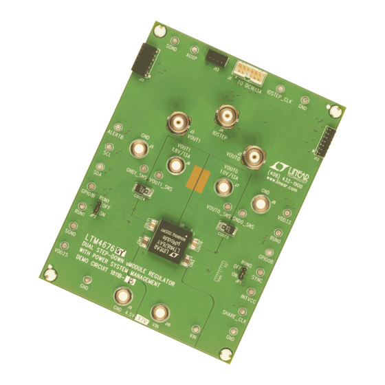
Figure 1. Dual-Output LTM4676A/DC1811B-B Demo Circuit
DEMO MANUAL DC1811B-B
Dual Step-Down µModule
2
PC and use ADI's I
C/SMBus/PMBus dongle DC1613A
to connect to the board. LTpowerPlay allows the user to
reconfigure the part on-the-fly and store the configuration
in EEPROM, view telemetry of voltage, current, tempera-
ture and fault status.
GUI Download
The software can be downloaded from:
For more details and instructions of LTpowerPlay, please refer
to LTpowerPlay GUI for LTM4676A Quick Start Guide.
Design files for this circuit board are
All registered trademarks and trademarks are the property of their respective owners.
LTM4676A
LTpowerPlay
available.
Rev. A
1
Advertisement

Related Manuals for Linear Technology Analog Devices LTM4676A


Summary of Contents for Linear Technology Analog Devices LTM4676A
- Page 1 DEMO MANUAL DC1811B-B LTM4676A Dual Step-Down µModule Regulator with PMBus Digital Power System Management DESCRIPTION PC and use ADI’s I C/SMBus/PMBus dongle DC1613A Demonstration circuit 1811B-B is a dual-output, high to connect to the board. LTpowerPlay allows the user to efficiency, high density, µModule regulator with 4.5V to ®...
-
Page 2: Quick Start Procedure
DEMO MANUAL DC1811B-B PERFORMANCE SUMMARY = 25°C) PARAMETER CONDITION VALUE Input Voltage Range 4.5V to 26.5V Output Voltage, V = 4.5V to 26.5V, I = 0A to 13A 0.5V to 5.5V (Minimum On)*, Default: 1V OUT0 OUT0 Maximum Output Current, I = 4.5V to 26.5V, V = 0.5V to 5.5V OUT0... - Page 3 DEMO MANUAL DC1811B-B QUICK START PROCEDURE – – LOAD1 LOAD0 (0A TO 13A) (0A TO 13A) – – OUT1 OUT0 – – 4.5V TO 26.5V – Figure 2. Proper Measurement Equipment Setup – Figure 3. Measuring Output Voltage Ripple Rev. A...
- Page 4 DEMO MANUAL DC1811B-B QUICK START PROCEDURE Input P ower Supply USB C able VIN Vout0 12-‐PIN ( J1) Load0 LTM4676A D emo USB t o I 2C/PMBus Dongle ...
- Page 5 DEMO MANUAL DC1811B-B QUICK START PROCEDURE OUT1 OUT0 (20MHz BW) (20MHz BW) 50mV/DIV 50mV/DIV 9.75A TO 13A 9.75A TO 13A LOAD STEP LOAD STEP Figure 7. Output Voltage V vs Load Current Figure 8. Output Voltage V vs Load Current OUT0 OUT1 Range = 0) Range = 1) OUT0...
-
Page 6: Ltpowerplay Software Gui
DEMO MANUAL DC1811B-B LTpowerPlay SOFTWARE GUI LTpowerPlay is a powerful Windows-based development issues when bringing up rails. LTpowerPlay utilizes the environment that supports Analog Devices power sys- DC1613A USB-to-SMBus controller to communicate with tem management ICs, including the LTM4676A, LTC3880, one of many potential targets, including the LTM4676A, LTC3883, LTC2974 and LTC2978. - Page 7 DEMO MANUAL DC1811B-B LTpowerPlay QUICK START GUIDE The following procedure describes how to use LTpowerPlay d. If you want to change the output voltage to a differ- to monitor and change the settings of LTM4676A. ent value, like 1.5V. In the Config tab, type in 1.5 in the VOUT_COMMAND box, like this: 1.
-
Page 8: Parts List
DEMO MANUAL DC1811B-B PARTS LIST ITEM REFERENCE PART DESCRIPTION MANUFACTURER/PART NUMBER Required Circuit Components CIN1 CAP ., 150µF, 35V, ALUMINUM ELECTR., SUN ELECT., 35CE150AX CIN2, CIN3, CIN4, CIN5 CAP ., X5R, 10µF, 35V, 10%,1210 MURATA, GRM32ER6YA106KA12 COUT1-COUT3, COUT6-COUT8 CAP ., X5R, 100µF, 6.3V, 20%, 1210 AVX, 12106D107MAT2A COUT4, COUT5 CAP ., 330µF, 6.3V, POSCAP , D3L... -
Page 9: Schematic Diagram
DEMO MANUAL DC1811B-B SCHEMATIC DIAGRAM Rev. A... - Page 10 DEMO MANUAL DC1811B-B SCHEMATIC DIAGRAM Rev. A...
- Page 11 DEMO MANUAL DC1811B-B SCHEMATIC DIAGRAM Rev. A Information furnished by Analog Devices is believed to be accurate and reliable. However, no responsibility is assumed by Analog Devices for its use, nor for any infringements of patents or other rights of third parties that may result from its use. Specifications subject to change without notice.
- Page 12 DEMO MANUAL DC1811B-B ESD Caution ESD (electrostatic discharge) sensitive device. Charged devices and circuit boards can discharge without detection. Although this product features patented or proprietary protection circuitry, damage may occur on devices subjected to high energy ESD. Therefore, proper ESD precautions should be taken to avoid performance degradation or loss of functionality. Legal Terms and Conditions By using the evaluation board discussed herein (together with any tools, components documentation or support materials, the “Evaluation Board”), you are agreeing to be bound by the terms and conditions set forth below (“Agreement”) unless you have purchased the Evaluation Board, in which case the Analog Devices Standard Terms and Conditions of Sale shall govern.
Need help?
Do you have a question about the Analog Devices LTM4676A and is the answer not in the manual?
Questions and answers