Table of Contents
Advertisement
Quick Links
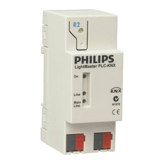
PLC-KNX
LightMaster Line Coupler
INSTALLATION MANUAL
WARNING
ISOLATE FROM MAINS SUPPLY PRIOR
TO INSTALLATION OR SERVICING. NO USER
SERVICEABLE PARTS INSIDE. INSTALLATION
AND SERVICE BY QUALIFIED PERSONNEL
ONLY
• Do not connect KNX TP1 bus to mains wiring.
• KNX TP1 bus is SELV (Safety Extra Low Voltage)
and it must be isolated and segregated from mains
and other wiring as per the local wiring rules and
KNX installation recommendations.
• Do not open the device.
• Do not expose this device to rain or moisture.
• Check a ll w iring t ermination p rior t o e nergizing t he
device.
• Installation, p rogramming a nd m aintenance m ust b e
carried out by qualified personnel only.
•
•
•
Features
• This device is designed for use on KNX TP1 communication bus as a:
– line coupler
– backbone coupler
– repeater
• It provides data transfer between two separate lines and also isolates
the bus lines from each other in order to enable the independent
local operation of a bus line and allow line extension.
Important Notes
System Software – This device is configured with the ETS PC software
System Commissioning – During system commissioning this device
must be a ssigned its own u nique physical address. Failure to d o t his can
result in malfunctions of other devices during initial start-up.
Installation – This device must only be installed and configured by
qualified professionals. If programming is required contact your local
agent for details.
Mounting L ocation – I nstall i n a d ry, w ell-ventilated l ocation i ndoor o nly.
KNX Data Cable – Use approved KNX TP1 data cable, segregate from
mains cable as per KNX installation recommendations and local wiring
rules. Connect devices in a 'daisy chain' . Do not cut or terminate live
cables.
Installation – Device must be installed by KNX certified personnel
and cabled in accordance to the standards detailed on the official KNX
Association website.
Electrical Diagram
Advertisement
Table of Contents

Related Manuals for Philips LightMaster PLC-KNX


Summary of Contents for Philips LightMaster PLC-KNX
- Page 1 PLC-KNX LightMaster Line Coupler INSTALLATION MANUAL Features • This device is designed for use on KNX TP1 communication bus as a: – line coupler – backbone coupler – repeater • It provides data transfer between two separate lines and also isolates the bus lines from each other in order to enable the independent local operation of a bus line and allow line extension. Important Notes System Software – This device is configured with the ETS PC software System Commissioning – During system commissioning this device must be a ssigned its own u nique physical address. Failure to d o t his can result in malfunctions of other devices during initial start-up. Installation – This device must only be installed and configured by qualified professionals. If programming is required contact your local agent for details. WARNING Mounting L ocation – I nstall i n a d ry, w ell-ventilated l ocation i ndoor o nly. •...
- Page 2 3. The primary line is connected via a bus terminal on the left side of the device. T he secondary line is connected via a bus terminal on the right side of the device. KNX Bus Permanent Connections 4. Re-check all terminations prior to energizing. 5. Energize K NX b us a nd c heck b us v oltage u sing a m ultimeter, KNX bus shall be between 21-30Vdc. 6. For programming instructions refer to the Philips LightMaster Commissioning guide. 7. This device must be assigned to its own unique physical address. Product Specifications Control Ports Compliance 2 x KNX port...
Need help?
Do you have a question about the LightMaster PLC-KNX and is the answer not in the manual?
Questions and answers