Sign In
Upload
Download
Table of Contents
Contents
Add to my manuals
Delete from my manuals
Share
URL of this page:
HTML Link:
Bookmark this page
Add
Manual will be automatically added to "My Manuals"
Print this page
×
Bookmark added
×
Added to my manuals
Manuals
Brands
Detnov Manuals
Control Panel
CCD-020
Installation manual
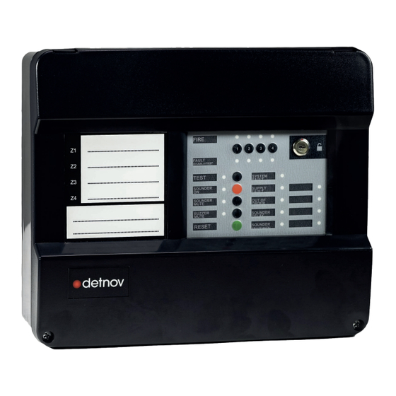
Detnov CCD-020 Installation Manual
Conventional fire detection control panel
Hide thumbs
1
2
3
Table Of Contents
4
5
6
7
8
9
10
11
12
13
14
15
16
17
18
19
20
21
22
23
24
25
26
27
28
29
30
31
32
33
34
35
36
37
38
39
40
page
of
40
Go
/
40
Contents
Table of Contents
Troubleshooting
Bookmarks
Table of Contents
Table of Contents
1 Introduction
About this Manual
European Standards
Explicit Definitions
Characteristics of the Control Panel
Inventory
Damage to the Unit
Requirements
Assembly Notes
Installation Notes
Operating Conditions
Disclaimer
2 General Description of the Series
3 Assembly Guide
Pre-Installation Checks
Installation Steps
Removing the
The Control Panel's Wiring
Location of the Control Panel on the Wall
Fixing the Control Panel to the Wall
Language Selection
4 Wiring Guide
Zone Wiring
Detector Wiring
Manual Call Point Wiring
Sounder Wiring
Sounder Timer
Wiring of 24 VDC Auxiliary Output
Wiring of Voltage-Free Relay Output
Power Supply Wiring
Battery Wiring
Wiring to the Mains
5 Start-Up Guide
System Verification
The System's Power Supply
Testing the System
6 User Guide
Indicator Lights
Audible Indicators
Control Keys
Operating Modes
Standby Mode
Alarm Mode
Fault Mode
Disconnected Mode
Test Mode
Out of Service Mode
System Fault Mode
What to Do in the Event of an Alarm
7 Maintenance Guide
The User
Daily Checks
Monthly Checks
The Maintenance Company
Weekly Checks
Yearly Checks
8 Troubleshooting
9 Characteristics
Advertisement
Quick Links
1
Wiring Guide
2
Indicator Lights
3
Troubleshooting
Download this manual
INSTALLATION MANUAL
EN
CCD-020 / CCD-040
Conventional fire detection control panel
Table of
Contents
Previous
Page
Next
Page
1
2
3
4
5
Advertisement
Table of Contents
Need help?
Do you have a question about the CCD-020 and is the answer not in the manual?
Ask a question
Questions and answers
Related Manuals for Detnov CCD-020
Control Panel Detnov CAD-250 User Manual
(34 pages)
Control Panel Detnov CAD-250 Installation Manual
(84 pages)
Control Panel Detnov CAD-250 Configuration Manual
(100 pages)
Control Panel Detnov CAD-150-8 User Manual
Analogue fire detection control panels (158 pages)
Control Panel Detnov CCD-040 Installation Manual
Conventional fire detection control panel (40 pages)
Control Panel Detnov CCD-100 Manual Manual
Conventional fire detection control panels (138 pages)
This manual is also suitable for:
Ccd-040
Table of Contents
Print
Rename the bookmark
Delete bookmark?
Delete from my manuals?
Login
Sign In
OR
Sign in with Facebook
Sign in with Google
Upload manual
Upload from disk
Upload from URL


Need help?
Do you have a question about the CCD-020 and is the answer not in the manual?
Questions and answers