Table of Contents
Advertisement
Quick Links
Advertisement
Table of Contents

Related Manuals for Detnov CAD-250


Summary of Contents for Detnov CAD-250
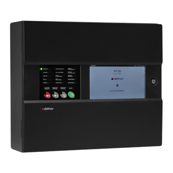
- Page 1 USER MANUAL...
-
Page 3: Table Of Contents
CONTENTS 1. INTRODUCTION 6.4. PRINTER ..................20 1.1. ABOUT THIS MANUAL ..............6 6.4.1. Printer ..................20 1.2. EUROPEAN STANDARDS .............. 6 6.4.2. Configuration ................20 1.3. EXPLICIT DEFINITIONS ..............8 6.5. PANEL TEST..................21 1.3.1. Notes on the use of this control panel ........8 7. - Page 4 Revision control Revision Comment Date First edition 29/11/2019 Typographical correction and regulatory references 05/12/2019 Specification of correction, typographical errors and contents 16/12/2019...
- Page 5 DISCLAIMER The manufacturer or distributors of this range of fire alarm panels cannot accept any responsibility for any misinterpretation of an instruction or guidance note or for full system compliance. The manufacturer's policy is of continuous improvement and we reserve the right to make changes to the product specifications at our discretion and without prior notice.
-
Page 6: Introduction
The purpose of this manual is to provide the user with all of the it meets the requirements of the following directives descriptions regarding procedures and technical details necessary to of the European Community. carry out the assembly, connection and start-up of CAD-250 fire alarm control panels. Directive Standard... -
Page 7: Explicit Definitions
1. INTRODUCTION 1.3. EXPLICIT DEFINITIONS In addition to these directives, the manufacturing of this control panel meets the following European directives for manufacturing and waste The procedures described in this manual include warnings and cautions management: to advise the user to adopt methodical and safe working practices ·... -
Page 8: Notes On The Use Of This Control Panel
(250 per loop). 1.3.3. Disclaimer Ethernet connection. The CAD-250 control panel is a fire prevention control panel that was Class A USB 1 ports for configuration with a pen drive created to comply with the most demanding operating conditions, whilst and 1 Class B for configuration from SC250 software. -
Page 9: Architecture
With 8 GB, the system can handle the information of any facility. 1.5. ARCHITECTURE The modular design of the CAD-250 control panel allows up to 3 modular components to be combined in a single structure of up to 4 sections or cabinets. -
Page 10: Main Panel
Indicates that there is a control element or Permanent relay disabled on the main board. PRINTER nly available on CAD-250-P: It allows you to obtain RESERVED 3 Amber Programmable indicator for customisable a paper copy of the system's events. This device function. -
Page 11: General Controls
1. INTRODUCTION 2. Main panel 2.2. GENERAL CONTROLS Function Symbol Description ACTIVATE Press the button to activate the SOUNDERS sounders. EVACUATION SILENCE Press the button to silence the SOUNDERS sounders. The sounders will reactivate if a new alarm event arrives. RELAYS Press the button to silence the DISABLED... -
Page 12: User Level
3. USER LEVEL If no event has occurred in the facility, the system will be in the STANDBY SCREEN. 3.1. STANDBY SCREEN If you press the padlock (��) that appears in the centre of the STANDBY Until an event occurs in the facility, the system states that it is SCREEN, you will enter the ACCESS SCREEN. -
Page 13: User Screen
3.3. USER SCREEN USER MENU Once you have entered the password, you will access the which is divided into: Name Posit. Description MAIN MENU Left Categorises the sections. Loops - Sectors - Manoeuvres - Log - Network - Configuration - Engineering - Maps SUBMENU Right Classifies the options for each menu... -
Page 14: Disablement Menu
2. ASSEMBLY GUIDE 4. DISABLEMENT MENU This feature allows you to deactivate a detection facility entity, whether it is an AREA, a ZONE or a DEVICE. To disable a zone, press: DISABLEMENT (Main menu) > Element tree Field Definition ENTITY It shows the entities that make up the facility, Area, Zone or individual device... - Page 15 When you press the selector of an entity, the behaviour of all associated entities in the hierarchy will change, being shown with a D (purple, disabled). On the main screen, there is the NAVIGATION BAR, where a series of buttons are shown that enable the following: It allows the sectorisation tree of the Area upper hierarchy to be collapsed or expanded.
-
Page 16: Log Menu
The EVENT LIST shows the following information, ordered from most 5. LOG MENU (historical event log) recent to oldest: The LOGS section shows you a list of all events recorded by the control panel. Field Definition To access the LOGS category, press the MAIN MENU: Event identifier, event sequence number. - Page 17 When filtering the event type, the NAVIGATION BAR counter will also update its value. Click one of the filter options on the submenu to view: ALL: All events are shown. ALARMS: Only the alarms are shown. FAULT: Only the faults are shown. TECHNICAL: Events that occur on technical inputs are shown.
-
Page 18: Settings Menu
6. SETTINGS MENU Main Menu Submenu Main View The settings category allows you to consult basic operating parameters of the control panel. To access the category, press: SETTINGS (Main menu) > GENERAL (Submenu) 6.1. GENERAL The GENERAL submenu is active by default and has 2 TABS: 6.1.1. -
Page 19: Versions
6.2. VERSIONS The version menu shows the software installed in the different components of the control panel. To access the submenu, press: SETTINGS (Main menu) > VERSIONS (Default submenu) This submenu allows you to consult the following values: Main Menu Submenu Main View Field... -
Page 20: Printer
6.4. PRINTER If your control panel model is the CAD-250-P, this submenu will Main Menu Submenu Main View be available. To access the SETTINGS category, press: SETTINGS (Main menu) > PRINTER (Submenu) This submenu has two tabs. 6.4.1. Printer The printer screen shows a series of parameters that can be activated via selectors. -
Page 21: Panel Test
6.5. PANEL TEST Main Menu Submenu Main View To access the TEST submenu, carry out the following steps: SETTINGS (Main menu) > TEST (Submenu) > > START (Button in the middle of the screen) During the test process, you should check that the LEDs of the MAIN PANEL and the screen work correctly. -
Page 22: Maintenance
7.3. CLEANING 7. MAINTENANCE The control panel must be cleaned regularly with a soft cloth dampened 7.1. LOG with water. Do not use solvents. According to the recommendations of the EN54 Part 14 standard, you should create a log in which you can record the following information: 7.4. - Page 23 Alarm counter Completion Date Time Incident Action required Person responsible reading date Consumable components: ......................Date on which they must be replaced: ....................................................................................................................................................
-
Page 24: Event Screen
8. EVENT SCREEN Name Description If an event occurs in the facility, the STANDBY SCREEN will change to this ALARM It shows if there is an active alarm, according to the EN54-2 standard. It includes a zones in alarm counter; the first zone in window. - Page 25 Name Description Name Description List filters according to status. Each icon includes a counter that indicates the number of On the right side of the screen there is a column of active events for each status. navigation icons The icon is highlighted when the counter shows 1 or more It allows access to higher user and configuration levels alarms.
-
Page 26: Troubleshooting
9.1. FAULTS SHOWN ON THE PRIMARY CONTROLS The LEDs and primary controls of the CAD-250 control panel allow the user to know the status of the facility quickly and to initiate a series of actions easily. These LEDs normally indicate anomalies in the detection network or control panel. -
Page 27: Faults Shown On The Event Screen
9.2. FAULTS SHOWN ON THE EVENT SCREEN Under the FAULTS icon in the EVENT SCREEN, the different system faults are shown. Below is a list of errors, causes and solutions for each of them: LEDS CAUSE SOLUTION SERVICE (Green) Switched on whenever the control panel is operating and powered. If there is no power or it is out of service, the LED will switch off. - Page 28 Under the FAULTS icon in the EVENT SCREEN, the different system faults are shown. Below is a list of errors, causes and solutions for each of them: DEVICES CAUSE SOLUTION Open fault This fault is due to the lack of end-of-line monitoring of some devices with this feature. Replace the end-of-line monitoring or change the switch and do not For example, the input modules where monitoring mode can be configured with a switch.
- Page 29 LOOPS CAUSE SOLUTION High temperature The charger temperature is above the maximum Check the battery connections. Out of service When the control panel is without power and the battery charge is below 20 V and is close Reconnect the power supply. to switching off.
-
Page 30: Technical Specifications
10. TECHNICAL SPECIFICATIONS The CAD-250 control panel was designed, manufactured and certified in accordance with the subsections of the following European standards: This fire control panel meets the subsections of the following European EN 54-4:1997, standards: EN 54-2:1997, EN 54-4:1997/AC:1999,... - Page 31 LOOP OUTPUTS WEIGHT: Without batteries: 12.5 kg EXPANSION 2 (upper and lower) With NP24-12 batteries: 30.5 kg OUTPUT VOLTAGE: 26 Vdc to 33 Vdc (Detnov protocol) INPUTS: measuring 50 mm x 15 mm ENVIRONMENTAL SPECIFICATIONS MAXIMUM LOAD: 0.45 A CONDUIT ENTRIES:...
- Page 34 MU 379 en 2020 c...
Need help?
Do you have a question about the CAD-250 and is the answer not in the manual?
Questions and answers