Advertisement
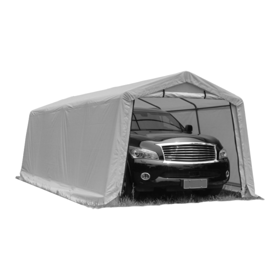
AUTO STORAGE SHELTER
TM
Ideal for all purpose outdoor storage
10' x 20' x 8' (3 x 6.1 x 2.4 m)
Assembly MANUAL
M odel NO.:103-1105N
Tools required for assembly (not included)
Advertisement
Table of Contents

Summary of Contents for Weather Fast 103-1105N
- Page 1 AUTO STORAGE SHELTER Ideal for all purpose outdoor storage 10' x 20' x 8' (3 x 6.1 x 2.4 m) ASSEMBLY MANUAL M odel NO.:103-1105N Tools required for assembly (not included)
- Page 2 TABLE OF CONTENTS IMPORTANT SAFETY INSTRUCTIONS…....................................................................................2 INTENDED USE PARTS LIST................................................3 ASSEMBLY PREPARATION ..........................................3 ASSEMBLY ................................................4-8 IMPORTANT SAFETY INSTRUCTIONS WARNING! Read all safety instructions to reduce the risk of injury or death. This is a temporary structure and is not recommended as a permanent structure. Choose your shelter's location carefully.
- Page 3 PARTS LIST Description Drawing Qty. Part# Leg Tube (Center Part) Leg Tube (Corner Part) Rafter Tube Roof Horizontal Tube Shoulder Horizontal Tube Bottom Cross Rails 4-Way Peak Connector 3-Way Side Connector-Left 3-Way Side Connector -Right Bent Corner Leg 4-Way Peak Connector 3-Way Peak Connector 4-Way Cross Rail Clamp 3-Way Cross Rail Clamp...
- Page 4 ASSEMBLY PREPARATION ● Place all parts from the packaging box in a cleared area and arrange them on the ground in front of you. ● Remove all packaging materials and place them back in the box. Do not dispose of the packaging materials until assembly is complete. ●...
- Page 5 Diagram B Diagram B Step 1: Preparing the Roof Parts Select level and suitable location for your shelter. Layout the roof parts as shown in Diagram B. Diagram C Please pay attention to the differences to the 5 connectors with reference to Diagram C below (connectors are also individually numbered).
- Page 6 Diagram F e. Repeat to assemble the other side( as shown in Diagram F). Diagram G Step 4: Assemble Bottom Cross Rails Install the Bottom Cross Rails(#6) between each two legs withCross Rail Clamps (Part#13 & #14) by the fittings (Part #22, #23 & 24). Part #13 is for Center Legs, and #14 is for Corner Legs.
- Page 7 Diagram J Step 6: Installing the Front and Back Covers. The front cover contains a zippered door to allow entry and exit to the shelter. Ensure to locate this cover to the desired end. Also, ensure the zipper is in the 'closed' position while installing. The back cover is a solid piece of polyethylene.
- Page 8 Diagram L Step 7: Installing the Main Cover To make sure the strap will stay in the sleeve when assembly thread the strap through the spindle of the ratchet. Raise and lower the handle two or three times to wind the Diagram L).
Need help?
Do you have a question about the 103-1105N and is the answer not in the manual?
Questions and answers
Can you connect 2 models 103-1105 together side by side ?
Purchasing replacement parts