Table of Contents
Advertisement
• FAST SHIPPING AND
DELIVERY
• TENS OF THOUSANDS OF
IN-STOCK ITEMS
• EQUIPMENT DEMOS
• HUNDREDS OF
MANUFACTURERS
SUPPORTED
• LEASING/MONTHLY
RENTALS
• ITAR CERTIFIED
SECURE ASSET SOLUTIONS
Artisan Technology Group
new and certified-used/p
SERVICE CENTER REPAIRS
Experienced engineers and technicians on s
at our full-service, in-house repair center
View
REMOTE INSPECTION
Instra
SM
Remotely inspect equipment before purchas
our interactive website at
Contact us:
(888) 88-SOURCE | sales@artisantg.com
www.instraview.c
Advertisement
Table of Contents
Troubleshooting

Summary of Contents for Leeson SPEEDMASTER WASHGUARD 174102
- Page 1 Artisan Technology Group new and certified-used/p • FAST SHIPPING AND SERVICE CENTER REPAIRS DELIVERY Experienced engineers and technicians on s at our full-service, in-house repair center • TENS OF THOUSANDS OF IN-STOCK ITEMS • EQUIPMENT DEMOS View REMOTE INSPECTION Instra •...
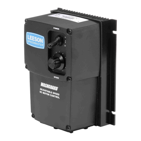
- Page 2 ® S P E E D M A S T E R ® 174102, 174103 & 174107 NEMA 4X SCR MOTOR CONTROLS...
- Page 3 C. Limitations of Liability - In the event of any claim or breach of any of LEESON’s obligations, whether expressed or implied, and particularly of any claim of a breach of...
-
Page 4: Safety Warnings
Warning It is possible for a drive to run at full speed as a result of a component failure. LEESON strongly recommends the installation of a master switch in the main power input to stop the drive in an emergency. -
Page 5: Table Of Contents
SPEEDMASTER™ OPERATION MANUAL Contents Warranty Statement Inside Front Cover Safety Warnings Specifications Dimensions Overview Installation Mounting ..........4 Removing the Plastic Cover . - Page 6 SPEEDMASTER™ OPERATION MANUAL Contents 174103 ..........19 174107 .
- Page 7 SPEEDMASTER™ OPERATION MANUAL Illustrations Figure 1. 174102, 174103 & 174107 Dimensional Diagrams ... . .2 Figure 2. Cover removal for terminal strip access .....6 Figure 3.
-
Page 8: Specifications
SPEEDMASTER™ OPERATION MANUAL Specifications Max. Armature HP Range HP Range Current with 115 VAC with 230 VAC Model (Amps DC) Applied Applied Style 174102 10.0 1/8–1 1/4–2 NEMA 4X 174103 10.0 1/8–1 1/4–2 NEMA 4X 174107 10.0 1/8–1 1/4–2 NEMA 4X AC Line Voltage 115 VAC or 230 VAC ±10%, 50/60 Hz, single phase Armature Voltage (115 VAC Input) -
Page 9: Dimensions
SPEEDMASTER™ OPERATION MANUAL Dimensions 5.63 [143] 5.16 [ 131] 0.19 [5.00] POWER SLOTTED HOLES 4 PLACES ® S P E E D M A S T E R SPEED 7.50 [191] 5.50 [140] ® ADJUSTABLE SPEED DC MOTOR CONTROL BOTTOM PLATE 0.73 [18.5] CONDUIT HOLES 2 PLACES... -
Page 10: Overview
SPEEDMASTER™ OPERATION MANUAL Overview The following is a quick-step guide to setting up the control. For more detailed installation information, read the Installation (page 4) and Calibration (page 10) sections of this user’s manual. 1. Mount the control using the 4 slotted holes on the heat sink. The slotted holes are 0.19 inches [5 mm] (see Figure 1). -
Page 11: Installation
SPEEDMASTER™ OPERATION MANUAL Installation Mounting 174102, 174103 and 174107 drives may be vertically wall mounted using the four 0.19 inch (5 mm) slotted holes on the attached heat sink (see Figure 1, Page 2). For motor loads less than 5 ADC, the drive may be bench mounted horizontally, or operated without mounting. -
Page 12: Connections
SPEEDMASTER™ OPERATION MANUAL Installation Table 1. Recommended Line Fuse Sizes FUSE SIZE (AMPS) FUSE SIZE (AMPS) MOTOR HP @ 115 VAC INPUT @ 230 VAC INPUT 1 1/2 – – Connections Warning Do not connect this equipment with power applied. Failure to heed this directive may result in fire or serious injury. -
Page 13: Figure 2. Cover Removal For Terminal Strip Access
Installation SPEEDMASTER™ OPERATION MANUAL POWER ® S P E E D M A S T E R SPEED ® ADJUSTABLE SPEED S T E P # 1 DC MOTOR CONTROL REMOVE THE SIX (6) PHILLIPS SCREWS ON THE FRONT CASE. NOTE: THE TWO SHORTER SCREWS (#6 - 32 x 2 ½) ON THE FRONT CASE ARE USED... -
Page 14: Figure 3. Drive Connections
SPEEDMASTER™ OPERATION MANUAL Installation MOV501 F502 L2 FRM SW L1 A2 TO SW A1 L2 TO SW L1 A2 FRM SW A1 F501 MOV503 TB501 230 VAC 115 VAC EARTH GROUND FIELD LINE VOLTAGE INPUT MOTOR (GREEN SCREW) OUTPUT (115 or 230 VAC) ARMATURE FIELD OUTPUT CONNECTIONS The field output is for shunt wound motors only. -
Page 15: Figure 3A. External Signal Connections, 174103.00
Installation SPEEDMASTER™ OPERATION MANUAL SIG MIN. SIG MAX SO501 P502 P501 PL501 DECEL ACCEL TQ LIMIT D501 D502 IR COMP MIN. SPD MAX SPD TB501 T501 RSH = 1000 OHM for 4 - 20 mA RSH = 250 OHM for 10 - 50 mA RSH = NOT USED for 1 - 5 mA RSH = NOT USED for 0 - 10V signal TERMINAL 2... -
Page 16: Field Output
SPEEDMASTER™ OPERATION MANUAL Installation Field Output The field output is for shunt wound motors only. Do not make any connections to F1 and F2 when using a permanent magnet motor. Use 18 AWG wire to connect the field output to a shunt wound motor. -
Page 17: Calibration
SPEEDMASTER™ OPERATION MANUAL Calibration Warning Dangerous voltages exist on the drive when it is powered. When possible, disconnect the voltage input from the drive before adjusting the trimpots. If the trimpots must be adjusted with power applied, use insulated tools and the appropriate personal protection equipment. -
Page 18: Figure 5. Calibration Trimpot Layout
SPEEDMASTER™ OPERATION MANUAL Calibration IL502 IC501 CURRENT LIMIT IL501 IC502 TRIMMER POTS TORQUE LIMIT (TQ LIMIT) ACCELERATION (ACCEL) DECELERATION (DECEL) TQ LIMIT ACCEL DECEL REGULATION (IR COMP) MINIMUM SPEED (MIN SPD) R501 MAXIMUM SPEED (MAX SPD) F502 L2 FRM SW L1 A2 TO SW A1 A2 FRM SW A1 F501... -
Page 19: Calibration Procedure
Calibration SPEEDMASTER™ OPERATION MANUAL Calibration procedure Calibrate the drive using the following procedure: Set the MIN SPD, IR COMP, ACCEL and DECEL trimpots to zero (full CCW). Set the TORQUE trimpot to maximum (full CW). Set the MAX SPD trimpot to midrange (approximate 12 o’clock position). -
Page 20: Maximum Speed (Max Spd)
SPEEDMASTER™ OPERATION MANUAL Calibration MAXIMUM SPEED (MAX SPD) The MAX SPD setting determines the motor speed when the speed adjust potentiometer is turned full CW or reference signal is at its maximum. It is factory set for maximum rated speed. To calibrate, set the MAX SPD trimpot full CCW. -
Page 21: Torque Limit (Torque)
Although TORQUE is set to 150% of drive nameplate current rating, continuous operating beyond that rating may damage the motor. If you intend to operate beyond the rating, contact your LEESON representative for assistance. The TORQUE setting determines the maximum torque for accelerating and driving the motor. -
Page 22: Acceleration (Accel)
SPEEDMASTER™ OPERATION MANUAL Calibration Remove power from the drive. Remove the lock from the motor shaft. 10. Remove the ammeter in series with the motor armature. ACCELERATION (ACCEL) The ACCEL setting determines the time the motor takes to ramp to a higher speed. See Specifications on page 1 for approximate acceleration times. -
Page 23: Figure 6. Recommended Torque And Ir Comp Settings
Calibration SPEEDMASTER™ OPERATION MANUAL 1 HP 2 HP 90 VDC 180 VDC 1750 RPM 1750 RPM 10 AMPS 9.2 AMPS 1/2 HP 1 HP 90 VDC 180 VDC 1750 RPM 1750 RPM 5 AMPS 5 AMPS 1/4 HP 1/2 HP 90 VDC 180 VDC 1750 RPM... -
Page 24: Operation
SPEEDMASTER™ OPERATION MANUAL Operation Warning Change voltage switch settings only when the drive is disconnected from AC line voltage. Make sure both switches are set to their correct position. If the switches are improperly set to a lower voltage position, the motor will not run at full voltage. -
Page 25: Startup
Operation SPEEDMASTER™ OPERATION MANUAL Startup Warning If the motor or drive does not perform as described in this section, disconnect the AC line voltage immediately. Refer to Troubleshooting, page 34, for further assistance. 174102 1. Set the speed adjust potentiometer (SPEED dial) to “0”, or full CCW. - Page 26 SPEEDMASTER™ OPERATION MANUAL Operation 174103 Manual Operation 1. Set the Signal/Manual Switch located on the enclosure to the MANUAL position. 2. Set the speed adjust dial to “0” (full CCW). 3. Apply AC line voltage 4. Set the POWER switch to the ON position 5.
- Page 27 SPEEDMASTER™ OPERATION MANUAL 174107 Warning Do not change the FORWARD / OFF / REVERSE switch while the motor is running. The motor must come to a complete stop before reversing. Changing motor direction before allowing the motor to completely stop will cause excessively high current to flow in the armature circuit, and may damage the drive and/or motor.
-
Page 28: Application Notes
Removing the connection between the inhibit pins allows the motor to accelerate to the speed set by the speed adjust potentiometer. LEESON offers an accessory plug harness for connecting to the INHIBIT terminals: part number 900282.01 [inhibit plug with 18 inches (46 cm) leads]. -
Page 29: Figure 7. Inhibit Plug With Run/Coast To Minimum Speed
Application Notes COAST TO MIN SPEED SO501 2-PIN HEADER Use LEESON accessory plug harness (part number: 900282.01) to mate with 2-pin header (SO501) on control board. Figure 7. Inhibit Plug with Run/Coast to Minimum Speed... -
Page 30: Decelerating To Minimum Speed
Application Notes Decelerating to minimum speed The switch shown in Figure 8 may be used to decelerate a motor to minimum speed. Closing the switch between S1 and S2 decelerates the motor from set speed to minimum speed determined by the MIN SPD trimpot setting. If the MIN SPD trimpot is set full CCW, the motor decelerates to zero speed when the switch between S1 and S2 is closed. -
Page 31: Dynamic Braking
Application Notes Dynamic Braking Warning Wait for the motor to completely stop before switching it back to the RUN position. This will prevent high armature currents from damaging the motor or drive. Dynamic braking may be used to rapidly stop a motor (Figure 9, page 25). -
Page 32: Figure 9. Dynamic Brake Connection
DYNAMIC BRAKE RESISTOR 15 ohm for 90 VDC motors 30 ohm for 180 VDC motors SO501 2-PIN HEADER Use LEESON accessory plug harness (part number: 900282.01) to mate with 2-pin header (SO501) on control board. Figure 9. Dynamic Brake Connection... -
Page 33: Multiple Fixed Speeds
Application Notes Multiple Fixed Speeds Replace the speed adjust potentiometer with series resistors with a total series resistance of 10K ohms (Figure 10). Add a single-pole, multi-position switch with the correct number of positions for the desired number of fixed speeds. TOTAL SERIES RESISTANCE 10K OHMS... -
Page 34: Adjustable Speeds Using Potentiometers In Series
Application Notes Adjustable speeds using potentiometers in series Replace the speed adjust potentiometer with a single-pole, multi- position switch, and two or more potentiometers in series, with a total series resistance of 10K ohms. Figure 11 shows a connection for fixed high and low speed adjust potentiometers. SPEED HIGH SPEED... -
Page 35: Independent Adjustable Speeds
Application Notes Independent adjustable speeds Replace the speed adjust potentiometer with a single pole, multi- position switch, and two or more potentiometers in parallel, with a total parallel resistance of 10K ohms. Figure 12 shows the connection of two independent speed adjust potentiometers that can be mounted at two separate operating stations. -
Page 36: Run/Jog Switch
JOG. Press the JOG pushbutton to jog the motor. Return the RUN/JOG switch to RUN for normal operation. PUSHBUTTON SO501 2-PIN HEADER Use LEESON accessory plug harness (part number: 900282.01) to mate with 2-pin header (SO501) on control board. Figure 13. RUN/JOG Switch Option #1... -
Page 37: Run/Jog Option #2
Application Notes RUN/JOG option #2 In the second wiring option, connect the RUN/JOG switch and the JOG pushbutton as shown in Figure 14. When the RUN/JOG switch is set to JOG, the motor decelerates to minimum speed (minimum speed is determined by the MIN SPD trimpot setting). -
Page 38: Leader-Follower Application
Application Notes Leader-follower application In this application, use a 174335 Process Control Module (PCM) to monitor the speed of the leader motor (Figure 15). The PCM isolates the leader motor from the follower drive, and outputs a voltage proportional to the leader motor armature voltage. The follower drive uses this voltage reference to set the speed of the follower motor. -
Page 39: Single Speed Potentiometer Control Of Multiple Drives
Application Notes Single speed potentiometer control of multiple drives Multiple drives can be controlled with a single speed adjust potentiometer using a 174335 Process Control Module (PCM) at the input of each drive to provide isolation (Figure 16). Optional ratio potentiometers can be used to scale the PCM output voltage, allowing independent control of each drive. -
Page 40: Reversing
DYNAMIC BRAKE RESISTOR MOTOR BRAKE SO501 2-PIN HEADER Use LEESON accessory plug harness (part number: 900282.01) to mate with 2-pin header (SO501) on control board. Figure 17. Reversing Circuit Connection... -
Page 41: Troubleshooting
SPEEDMASTER™ OPERATION MANUAL Troubleshooting Warning Dangerous voltages exist on the drive when it is powered. When possible, disconnect the drive while troubleshooting. High voltages can cause serious or fatal injury. Before troubleshooting Perform the following steps before starting any procedure in this section: •... -
Page 42: Power And Current Limit Leds
Troubleshooting Power and Current Limit LEDs 174102, 174103 & 174107 drives are equipped with a green, PCB-mounted power LED and a red, PCB-mounted current limit LED. POWER LED (IL502) The green power LED turns on when AC line voltage is applied to the drive. -
Page 43: Troubleshooting Tables
Troubleshooting SPEEDMASTER™ OPERATION MANUAL Symptom Possible Suggested Causes Solutions Fuse blows or circuit 1. Line fuses or circuit 1. Check that line fuses breaker trips breakers are the or circuit breakers wrong size. are the proper size. 2. Motor cable or 2. - Page 44 SPEEDMASTER™ OPERATION MANUAL Troubleshooting Symptom Possible Suggested Causes Solutions Line fuse does not 3. Drive is in current 3. Verify that the motor blow or circuit limit. is not jammed. breaker does not Increase TORQUE trip, but the motor setting (page 14). does not run (cont.) 4.
- Page 45 Troubleshooting SPEEDMASTER™ OPERATION MANUAL Symptom Possible Suggested Causes Solutions Motor pulsates or 1. IR COMP is set too 1. Adjust the IR COMP surges under load high. setting slightly CCW until the motor speed stabilizes (page 13). 2. Control is in current 2.
-
Page 46: Replacement Parts
Table 3 is provided as a guide for some component parts that may require replacement. These items are not available from LEESON. They are readily available from suppliers of electronic components. Replacing these items on drives that are under warranty will void the warranty. - Page 47 SPEEDMASTER™ OPERATION MANUAL NOTES...
- Page 48 SPEEDMASTER™ OPERATION MANUAL NOTES...
- Page 49 SPEEDMASTER™ OPERATION MANUAL NOTES...
- Page 50 LEESON Electric assumes no responsibility for any errors that may appear in this manual and makes no commitment to update or to keep current the information in this manual.
- Page 51 Artisan Technology Group new and certified-used/p • FAST SHIPPING AND SERVICE CENTER REPAIRS DELIVERY Experienced engineers and technicians on s at our full-service, in-house repair center • TENS OF THOUSANDS OF IN-STOCK ITEMS • EQUIPMENT DEMOS View REMOTE INSPECTION Instra •...
Need help?
Do you have a question about the SPEEDMASTER WASHGUARD 174102 and is the answer not in the manual?
Questions and answers