Advertisement
Quick Links
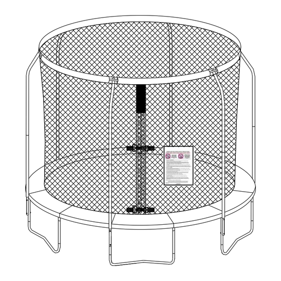
14FT (426CM)TRAMPOLINE AND "STEEL FLEX"
METAL RING ENCLOSURE COMBO SET
Assembly, Installation, Care, Maintenance and Use Instructions
MODEL NUMBER # TR-14-FLEX-FZ
SAFETY INFORMATION, INSTALLATION AND MAINTENANCE INSTRUCTIONS:
READ THESE MATERIALS PRIOR TO ASSEMBLING AND USING THE TRAMPOLINE
THESE INSTRUCTIONS ARE IMPORTANT TO MINIMIZE CHANCES OF INJURY. PLEASE READ
EACH OF THEM THOROUGHLY BEFORE YOU ASSEMBLE AND USE THIS TRAMPOLINE.
RETAIN THIS MANUAL FOR FUTURE REFERENCE.
DO NOT ALLOW CHILDREN TO USE UNLESS SUPERVISED BY AN ADULT
MAXIMUM WEIGHT OF THE USER SHALL NOT EXCEED 220LBS (100KG).
TRAMPOLINE MUST ALWAYS BE USED WITH THE ENCLOSURE.
ALL OF THE PARTS ARE ONLY TO BE USED AS FOR TRAMPOLINE.
SOME FOAM TUBE DEFORMATION MAY TAKE PLACE DURING TRANSPORT. IT'S NORMAL AND IT
SHOULD RECOVER OVER TIME.
USER'S MANUAL
KEY CODE: 41790038
WARNING
CUSTOMER SERVICE
Toll Free: 1-800-333-061
MONDAY-FRIDAY, 9 A.M. - 5 P.M. CENTRAL TIME
NOTICE
DO NOT ALLOW
MORE THAN ONE
PERSON ON THE
TRAMPOLINE AT A
TIME.
Advertisement

Related Manuals for Tasman Sports TR-14-FLEX-FZ

Summary of Contents for Tasman Sports TR-14-FLEX-FZ
- Page 1 14FT (426CM)TRAMPOLINE AND "STEEL FLEX" METAL RING ENCLOSURE COMBO SET Assembly, Installation, Care, Maintenance and Use Instructions USER’S MANUAL DO NOT ALLOW MORE THAN ONE MODEL NUMBER # TR-14-FLEX-FZ PERSON ON THE TRAMPOLINE AT A KEY CODE: 41790038 TIME. WARNING...
- Page 2 INTRODUCTION Thank you for purchasing this product! This trampoline was designed and manufactured with quality materials and craftsmanship, providing fun and exercise in the enjoyment of your own backyard. It is very important that the owners and users of this trampoline have adequate knowledge of techniques and rules for proper use.
-
Page 3: Important Safety Instructions
IMPORTANT SAFETY INSTRUCTIONS BEFORE YOU BEGIN: Review all steps before beginning assembly and read all precautions before using the trampoline. The owner and supervisors of the trampoline are responsible to make all users aware of practices specified in these instructions. Save this manual for future reference. - Page 4 ALWAYS maintain clear space on all sides of the trampoline. Place the trampoline away from walls, structures, fences and other play equipment. Clear any obstructions beneath or around the trampoline, for example tree limbs or trunks, wires or other possible hazards. ...
- Page 5 WARNING ALWAYS START YOUR JUMP AT THE CENTER OF TRAMPOLINE MAT. PARALYSIS OR DEATH CAN NO MORE THAN ONE PARALYSIS OR DEATH CAN NO MORE THAN ONE RESULT IF YOU LAND ON PERSON AT A TIME ON THE RESULT IF YOU LAND ON PERSON AT A TIME ON THE YOUR HEAD OR NECK! TRAMPOLINE!
- Page 6 How to Inspect the Trampoline Net for Proper Use Always check the enclosure netting for signs of UV damage, deterioration, brittleness, cracking, and tearing every time before using the trampoline and enclosure. Step 1 - Inspect the enclosure netting before EACH use for wear or tear by pinching and pulling a section of the netting between fingers and pulling downward.
-
Page 7: Assembly And Installation Instructions
ASSEMBLY AND INSTALLATION INSTRUCTIONS Review all steps before assembly and read all precautions before using this product. Failure to do so can result in serious injury or death. During periods of non-use, this trampoline and trampoline enclosure can be easily disassembled and stored by reversing the order of installation. - Page 8 PART LIST FOR TRAMPOLINE Part Number Description Quantity Number Trampoline Mat, stitched with TM-14-72-28 Triangle-Rings TFP-14-28-PE Frame Pad TRLS-14-72-42 Top Rail with Leg Sockets TR-14-72-42 Top Rail TLB-14-38.1 Leg Base TVL-14-38.1 Vertical Leg Extension(one hole) TVLH-14-38.1 Vertical Leg Extension (two holes) Galvanized Springs –...
- Page 9 HARDWARE USE FOR TRAMPOLINE AND ENCLOSURE Part Number Number TSLT Wrench EGS2W-14 #E Gap Spacer x 12pcs ESLW-14 ECN-14 #G Spring Lock #J Arc Washer x 12pcs Washer x 12pcs #10 Small Spring ESLS-14 Lock Washer x 6 pcs #I Self-locking Screw x18pcs EAW-14 Allen Wrench...
-
Page 10: Trampoline Frame Assembly
TRAMPOLINE FRAME ASSEMBLY STEP 1 – Leg Support Assembly There are a total of 30 pieces of steel tubing parts that are needed to assemble the trampoline frame. All parts with the same part # are interchangeable and have no “right” or “left” orientation. To connect the parts, simply slide a section tubing that is smaller on one end into the adjacent section that has a larger opening. - Page 11 STEP 2 – Support Assembly Slide one Vertical Leg extension (# 6A) and the other one Vertical Leg extension (two holes) (# 6B) into the Leg Base (# 5) as shown in FIGURE 2. Repeat this step for all the Leg bases. # 6A # 6B FIGURE 2...
- Page 12 STEP 3 – Top Rail Assembly A. Two people will be necessary at this point to assemble the trampoline. One person lifts the Support assembly from STEP 2 to a standing (vertical) position and inserts one of the sockets of the Top Rail with Leg Sockets (# 3) into the Vertical Leg Extension portion of the Support Assembly.
- Page 13 C. Screw in the Self-locking Screw (# I) and Small Spring Washer (# 10) with Allen Wrench (# K) as shown in FIGURE 5. Don’t completely tighten the Self-Locking Screws until instructed in the next step. After the next step is completed and all springs are attached, the Self-Locking Screws will need to be tightened completely.
- Page 14 STEP 4 – Trampoline Mat Assembly A. Lay out the Trampoline Mat (# 1) inside the frame with warning labels facing up as shown in FIGURE 6. There are total of 72 Triangle-Rings sewn on the mat and 72 holes on the Top Rail Frame. None are numbered, so please follow the instructions carefully to ensure proper installation.
- Page 15 B. Select an arbitrary point on the Frame (call it Point “ZERO”). Hook one end of the Spring (# 7) into the triangle-ring on the Mat (# 1). Holding the Spring Loading Tool underhand, pull the other end of the Spring towards point “ZERO”...
- Page 16 C. Count holes 36 on the Top Rail and corresponding Triangle-Rings, you should be at point 36. Attach a spring at this point as shown in FIGURE 8 ZERO SPRING (# 7) TRAMPOLINE MAT (#1) FIGURE 8...
- Page 17 D. From point 36, count back 18 holes on the Top Rail and Triangle-Rings, you should be at point 18. Attach a spring at this point as shown in FIGURE 9. ZERO SPRING (# 7) TRAMPOLINE MAT (#1) FIGURE 9...
- Page 18 E. Count another 18 holes from point 36 on the Top Rail and Triangle-Rings, you should be at point 54. Attach a spring at this point as shown. At this point in assembly, you should have 4 springs install at ZERO, 18, 36 and 54.
- Page 19 F. Attach a spring at every 6 holes and corresponding Triangle-Rings. For even distribution of tension and ease of assembly, springs should be placed on opposite sides of the mat/frame…..i.e. 6 then 42, 12 then 48, 60 then 24, 66 then 30, etc. In addition to the previously installed springs, you should have springs at 6, 12, 24, 30,42,48, 60 and 66 as shown in FIGURE 11.
- Page 20 G. Attach a spring every 3 holes and corresponding Triangle-ring. For even distribution of tension and ease of assembly, springs should be placed on opposite sides of the mat/frame. i.e. 3 then 39, 57 then 21, etc. In addition to the previously installed springs, you should have springs at 3, 9, 15, 21, 27, 33, 39, 45, 51, 57, 63 and 69 as shown in FIGURE 12.
- Page 21 H. Then, attach the remaining 48 springs by using the same theory of counting equal holes as shown in FIGURE 13. FIGURE 13 STEP 5 – Trampoline Safety Placard Attachment Using the tie wrap, attach the Trampoline Safety Instruction Placard (# 8) to the trampoline. The tie wrap should go around the Vertical Frame Joint and the Top Rail to ensure that it doesn’t slide off the trampoline.
-
Page 22: Frame Pad Assembly
FRAME PAD ASSEMBLY WARNING Never use the trampoline without attaching the frame pad. Properly tie down the frame pad before each use!! STEP 6 A. Lay the Frame Pad (# 2) over the trampoline so that the springs and steel frame are fully covered. Please ensure that the Frame Pad covers all metal parts. - Page 23 B. Finally, wrap the inner elastic straps around the Triangle-Rings and tie a knot first as shown in ENLARGED DIAGRAM, then tie it into a one-sided as shown in FIGURE 16. Make sure that both the knot and the bow are tight and that the Frame Pad is securely attached to the trampoline. Repeat this step for all of the straps.
-
Page 24: Trampoline Enclosure Assembly
TRAMPOLINE ENCLOSURE ASSEMBLY BEFORE YOU BEGIN: Review all steps before beginning the assembly and read all precautions before using the trampoline. All the tools needed are included with this package. At least two adults are required to assemble the trampoline. NOTICE: SOME FOAM TUBE DEFORMATION MAY TAKE PLACE DURING TRANSPORT. - Page 25 B. Pull the foam downward a little bit to locate the hole at the curved end of Upper Frame Tube with Foam (# Attach the Plastic Cap (# P) to Upper Frame Tube with Foam (# A), secure by using Self-Locking Screw (# I) and Allen Wrench (# K) as shown in FIGURE 18.
- Page 26 C. Connect the Lower Frame Tube with Foam (# B) to the trampoline Leg Frame as shown in FIGURE 19. One person will need to hold the Leg Frame steadily while another installs the Frame Tube. 1. Align the holes on the Lower Frame Tube with Foam (# B) with the Leg Frame. 2.
- Page 27 D. Separate all the Cable Wire (# C) into two groups and assemble them with Wrench (# D) as shown in FIGURE 20. CAUTION: TWO ADULTS ARE REQUIRED Please ensure that all connection points of the Cable Wires are securely tightened together by Wrench.
- Page 28 E. Insert the two groups of Cable Wires into the sleeves as shown in FIGURE 21. By doing so, all the top sleeves will be divided into two groups with each one having a group of Cable Wires in it. ENLARGED DIAGRAM FIGURE 21...
- Page 29 F. Two people will be needed to complete this step. Slide the 2 assembled Cable Wires through the sleeve at the top of the Enclosure Netting (# M) as shown in FIGURE 22 and then connect the two ends of the assembled Cable Wires together using Wrench (# D).
- Page 30 CAUTION: TWO ADULTS ARE REQUIRED G. Attach Upper Frame Tube with Foam (# A) with the Plastic Cap (installed in STEP 6 PART B above) to the Cable Wire as shown in FIGURE 23. Make sure that the Cable Wire fits into the slot properly. Repeat in the same manner for all six frame tubes.
- Page 31 H. Now, connect the assembled Upper Frame Tube with Foam (# A) with the Enclosure Netting (attached in the earlier step) to the Lower Frame Tube with Foam (# B) as shown in FIGURE 25. “RING” ENLARGED DIAGRAM FIGURE 25...
- Page 32 Secure Upper Frame Tube with Foam (# A) to Lower Frame Tube with Foam (# B) by inserting Self-Locking Screw (# I) and tighten using Allen Wrench (# K) as shown in FIGURE 26. Hint: In order to locate the holes to fit the screw, the foam on the Upper Frame Tube with Foam (# A) and Lower Frame Tube with Foam (# B) may need to be pushed aside Hole ENLARGED...
- Page 33 J. Fasten the bottom of the trampoline netting to the trampoline. 1. Lift the Trampoline pad and tie one end of Cord (# L) to the Triangle-Ring on the Trampoline Mat Triangle- Ring as shown in FIGURE 27. 2. Loop the other end of the cord through a hole on the edge of the net and then strand through the adjacent triangle-ring on the mat.
- Page 34 K. Close the zip of the Enclosure Netting of the door which should be located center above a Leg Base of the trampoline, then snap both of the buckles as shown (the lower buckle is not shown) in FIGURE 28. ENLARGED DIAGRAM FIGURE 28...
-
Page 35: Care And Maintenance Instructions
CARE AND MAINTENANCE INSTRUCTIONS Warning! Failure to follow these instructions to ensure proper operational condition of your trampoline may lead to serious injury or death. The springs, trampoline legs and enclosure netting must be inspected prior to every use. The legs should be locked securely into place, all the springs attached to the frame and there should be no tears in the enclosure netting. -
Page 36: Proper Use Instructions
PROPER USE INSTRUCTIONS Read and understand the use instructions in this manual prior to using this product. Failure to do so can result in serious injury or death. MAXIMUM USER WEIGHT: Maximum weight of user should not exceed 220lbs (100kg). Trampolines over 20 inches (500mm) tall are not recommended for use by children under 6 years of age. - Page 37 Read and understand the use instructions in this manual prior to using this product. Failure to do so can result in serious injury or death. Responsibilities of the user The key here is to stay in control of your jumps. DO NOT move onto more complicated, more difficult maneuvers until you have mastered the basic, fundamental bounce.
- Page 38 LESSON PLAN WARNING: ALWAYS START YOUR JUMP AT THE MIDDLE OF TRAMPOLINE MAT INDICATED BY WHITE CIRCLE The following lessons are suggested for you to learn basic steps and bounces. Before using the trampoline, you should read and understand all warnings. A complete discussion and demonstration of body mechanics and trampoline guidelines should occur between the supervisor and student as well.
- Page 39 4. Land in the Prone position and return to standing position TASMAN SPORTS SHEEHAN ROAD, WESTHEIDELBERG, VICTORIA SERVICE PHONE NUMBER 1800-333-061 MODEL NUMBER # TR-14-FLEX-FZ KEY CODE: 41790038 TR-14-FLEX-FZ-KM001...
Need help?
Do you have a question about the TR-14-FLEX-FZ and is the answer not in the manual?
Questions and answers