
Subscribe to Our Youtube Channel
Related Manuals for Fluidigm Hyperion


Summary of Contents for Fluidigm Hyperion
- Page 1 PN 400311 B1 Hyperion Imaging System User Guide Hyperion Imaging System User Guide...
- Page 2 Fluidigm Canada PN 400311 B1 IMC-QSG-02 For technical support visit fluidigm.com/support. North America +1 650 266 6100 | Toll-free (US/CAN): 866 358 4354 | support.northamerica@fluidigm.com Latin America +1 650 266 6100 | techsupportlatam@fluidigm.com Europe/Middle East/Africa/Russia +44 1223 598100 | support.europe@fluidigm.com Japan +81 3 3662 2150 | techsupportjapan@fluidigm.com...
-
Page 3: Table Of Contents
C hapter : Maintenance 4 2 T 4 2 T 4 2 T 4 2 T O perator Safety for the Hyperion Imaging System C leaning Instructions 4 2 T 4 2 T 4 2 T... -
Page 4: About This Guide
Operator Safety for the Hyperion Imaging System The Hyperion™ Imaging System is classified as a Class 1 laser device. The laser radiation of the Class 1 laser system is eye-safe under all operating conditions. -
Page 5: Safety Alerts For Instruments
Safety Data Sheets Read and understand the SDSs before handling chemicals. To obtain SDSs for chemicals ordered from Fluidigm, either alone or as part of this system, go to fluidigm.com/sds search for the SDS using either the product name or the part number. -
Page 6: C Hapter : Hyperion Imaging System
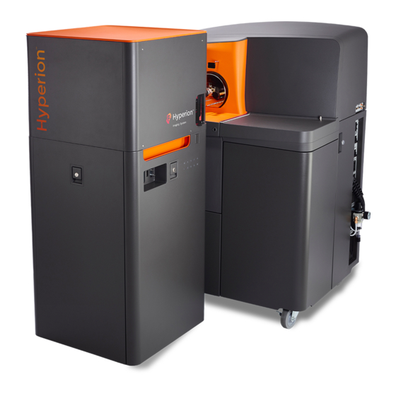
Chapter 1: Hyperion Imaging System Introduction and Specifications Introduction The Hyperion™ Imaging System is the world’s first and only commercially available metal-tagged, antibody-directed Imaging Mass Cytometry™ (IMC™) platform that allows highly multiplexed imaging with 135 available channels. The system is designed to detect metal-tagged antibodies bound to proteins in biological samples using standard staining methods. - Page 7 (ICP) torch through the argon and helium flow. Figure 2. A glass slide containing a biological sample is loaded into the Hyperion Imaging System. The beam from the solid-state laser is directed to the sample on the slide. The resulting plume is directed through the coupling tube in a stream of argon gas towards the ICP Torch for CyTOF detection.
- Page 8 MCD™ Viewer software. MCD Viewer can also export acquired data as separate images in a TIFF file format. Figure 3. Schematic of the Hyperion Imaging System coupled with the Helios system. P lume Transients 8 6 B 8 1 B The material resulting from the laser shot that is directed to the sample slide is referred to as the plume.
-
Page 9: Solid-State Laser Specifications
Chapter 1: Hyperion Imaging System Introduction and Specifications Solid-State Laser Specifications Figure 4. Graph of L u intensity. The plume width of a single plume is represented as 384 pushes during 20 Hz operation. A 20 Hz frequency is used to record and optimize transients during tuning. -
Page 10: Hyperion Imaging System Specifications
Chapter 1: Hyperion Imaging System Introduction and Specifications Hyperion Imaging System Specifications Hyperion Imaging System Specifications Table 2. System specifications for the Hyperion Imaging System Description System Specification Tissue thickness (full ablation) ≤ µm thickness Addressable sample size ≥ mm x mm Scan area ≥... - Page 11 Chapter 1: Hyperion Imaging System Introduction and Specifications Hyperion Imaging System Specifications Table 5. Instrument dimensions for the Hyperion Tissue Imager (HTI™) Description Instrument Dimensions Height cm ( in) Width cm ( in) Depth cm ( in) Weight ...
- Page 12 cm ( in) Width cm ( in) Depth cm ( in) Weight kg ( lb) Table 7. Input and output connections for the Hyperion Imaging System Description Input and Output Connections Power AC power Gases Argon gas, Helium gas...
-
Page 13: Standard Equipment
.–. Length .–. Thickness 0.8–1.7 * Recommendations are based on the size of the Hyperion Imaging System slide stage. Consumables and Reagents H yperion Imaging System 3 5 B Table 11. Consumables available for the Hyperion Imaging System Part Number... -
Page 14: Helios
Refer to the Helios User Guide (PN 400250). Consumables Ordering North America Customers in the US and Canada who have a Fluidigm account are already registered for online ordering. Go to fluidigm.com/catalog . New customers can set up an online account to... -
Page 15: C Hapter : Instrument Overview
Chapter 2: Instrument Overview Hyperion Tissue Imager WARNING Laser instruments generate potentially hazardous UV radiation. Do not remove the top cover of the Hyperion™ Tissue Imager. Only a Fluidigm field service engineer should remove the top cover and perform maintenance. Top cover... - Page 16 Chapter 2: Instrument Overview Hyperion Tissue Imager Coupling window Coupling attachment Ablation chamber Figure 6. Schematic of the Hyperion Tissue Imager back view Hyperion Imaging System: User Guide...
- Page 17 When the sample window or the coupling window is in the open position, the light corresponding to that window on the LED panel on the right side of the instrument is NOT LIT and the user cannot perform tuning or acquisition on the system. Hyperion Imaging System User Guide...
-
Page 18: Hyperion Tissue Imager Led Panel
Chapter 2: Instrument Overview Hyperion Tissue Imager LED Panel Hyperion Tissue Imager LED Panel Table 13. Instrument Interlock LEDs on the LED panel of the Hyperion Tissue Imager Instrument Interlock LED Description COUPLING WINDOW When the light is green, the coupling window is closed. - Page 19 Chapter 2: Instrument Overview Hyperion Tissue Imager LED Panel Instrument Interlock LED Description POWER When the light is continuously green, the system power supplies are on. When light is not lit, the system power supplies are off. UPPER COVERS When the light is not lit, the upper cover housing the optics and the laser has been removed.
- Page 20 Chapter 2: Instrument Overview Hyperion Tissue Imager LED Panel Front shield RF fingers Load coil Torch body Figure 8. Torch box Hyperion Imaging System: User Guide...
-
Page 21: Other Components
Chapter 2: Instrument Overview Other Components Other Components Table 15. Other Helios components Parts Image Location AC distribution Right side of Helios system Sampler Cone In the vacuum interface Hyperion Imaging System User Guide... - Page 22 Chapter 2: Instrument Overview Other Components Parts Image Location Cooling fans Inside lower front door Hyperion Imaging System: User Guide...
-
Page 23: C Hapter : Operation
For more details, see Helios, a CyTOF System Site Requirements Guide (PN 400252). Inspect both ends of the Hyperion Tissue Imager (HTI™) Injector to check for debris or material prior to beginning this procedure. Inspect under a microscope (if available). - Page 24 Chapter 3: Operation Connect the Hyperion Tissue Imager to Helios Insert the Injector into the Torch Assembly. Gently rotate the Injector to push it past the O-rings until it is fully seated into the Torch Assembly. WARNING Finger cut hazard. Broken glass may cause injury or cutting of fingers or hands.
- Page 25 Chapter 3: Operation Connect the Hyperion Tissue Imager to Helios Inspect the coupling tube to ensure that there is no debris or dust (use compressed air to remove any dirt from the coupling), and then connect the larger-diameter nut to the injector.
- Page 26 Chapter 3: Operation Connect the Hyperion Tissue Imager to Helios Carefully slide the alignment tool onto the heater guide pins of Helios, ensuring that the back of the tool is flush against the Torch Assembly. Secure the tool in position with one hand and tighten the right-side thumbscrew.
- Page 27 Chapter 3: Operation Connect the Hyperion Tissue Imager to Helios With the first thumbscrew secure, reach down from above with your other hand and tighten the thumbscrew on the left. After both screws are secure, ensure that the alignment tool is level on the heater guide pins and that the back of the tool is against the Torch Assembly.
- Page 28 Loosen the knob and extend the arm of the alignment tool fully. Tighten the knob to lock the arm in place. Raise the Hyperion Tissue Imager completely by pressing the up arrow on the wheel retraction switch until the tissue imager is fully in the raised position. Lift the coupling window using the gray tab.
- Page 29 Loosen the knob on the alignment tool and push in the arm of the alignment tool all the way back toward the Helios instrument. With an arm over the top of the Hyperion Tissue Imager, press down on the wheel retraction switch to lower the module until it is seated on the ground. Watch for any shifting of the Hyperion Tissue Imager as it settles.
- Page 30 Chapter 3: Operation Connect the Hyperion Tissue Imager to Helios Position the Hyperion Tissue Imager in front of Helios so that the Helios Injector aligns with the connection opening in the ablation chamber on the Hyperion Tissue Imager. Slide the Injector fitting over the back end of the injector in Helios. Grip the back nut with one hand while tightening the Injector fitting in the clockwise direction.
- Page 31 Chapter 3: Operation Connect the Hyperion Tissue Imager to Helios Insert the coupling tube end into the coupling attachment in the ablation chamber. IMPORTANT The tube must be as straight as possible. If the tube is not straight then raise the instrument up using the wheel retraction switch so that the castors are exposed, and adjust the instrument position.
- Page 32 Chapter 3: Operation Connect the Hyperion Tissue Imager to Helios Tighten the ablation chamber nut to the ablation chamber in the clockwise direction. Close the coupling window. Ensure that all the communication cables. have been connected. Connect the USB 2.0 cable connects to the computer for software control.
-
Page 33: Start The Hyperion Imaging System
Turn the instrument on by clicking the I/O power switch on the communication panel to the I position. The Hyperion Tissue Imager is now connected to Helios and is ready for operation. WARNING TRIP HAZARD. Watch your step to avoid falling over objects. - Page 34 Chapter 3: Operation Start the Hyperion Imaging System If you already have a CyTOF user account, enter the your username and password. Click L og on 5 7 T 5 7 T If you are a new user, in the U sername text box, enter Administrator.
-
Page 35: Unload And Load The Tuning Slide Or Sample Slide
On the Instrument Control tab, click Unload Sample. After the stage on the Hyperion™ Tissue Imager fully extends, open the sample window and, if necessary, remove the previously loaded slide. Hyperion Imaging System User Guide... - Page 36 Place the slide in the grooves on the stage and insert. Push the slide until it is firmly seated. A loud noise occurs if the slide is inserted incorrectly. Hyperion Imaging System: User Guide...
- Page 37 14,700 µm from the left side of the inserted microscope slide and 13,300 µm from the bottom of the slide, which is considered the midpoint of the slide. The slide coordinate system starts on the bottom left-hand corner of the slide, which represents X=0 and Y=0. Hyperion Imaging System User Guide...
-
Page 38: Start The Laser
In the Toolbar click Start Laser to turn on the laser power. Check the HTI Status Panel to confirm that the laser is on (blue circle). NOTE See CyTOF Software v7.0 Help for procedures related to instrument control, tuning, and data acquisition. Hyperion Imaging System: User Guide... -
Page 39: Disconnect The Hyperion Tissue Imager From Helios
Disconnect communication cables and gas lines including USB 2.0 connection, USB 3.0 connection, trigger, argon, and helium gas lines. On the Hyperion Tissue Imager ablation chamber, loosen the black nut on the coupling tube. Disconnect the coupling interlock. Hyperion Imaging System User Guide... - Page 40 Chapter 3: Operation Disconnect the Hyperion Tissue Imager from Helios Using the wheel retraction switch on the right side of the instrument, raise the instrument. NOTE The wheel retraction switch is disabled when the coupling tube is connected to the ablation chamber.
-
Page 41: Switch To Cell Suspension Mode
Turn off the radio frequency (RFG) circuit breaker on the on the right side of the Helios instrument. Disconnect the AC power cord from the AUXILIARY connection panel. Carefully roll the Hyperion Tissue Imager to a safe area in the laboratory using the instrument castors. - Page 42 Chapter 3: Operation Disconnect the Hyperion Tissue Imager from Helios Disconnect the coupling tube and move the Hyperion Tissue Imager out of the way to access the injector. Gently twist and pull the Injector from the torch assembly. Hyperion Imaging System: User Guide...
- Page 43 Chapter 3: Operation Disconnect the Hyperion Tissue Imager from Helios Insert the HT Injector (PN 107018) into the torch body and push in until it can go no farther. Reconnect the heater box to the torch assembly. Slide the heater box onto the support pins towards the torch assembly so that the spray chamber ball joint connection meets the injector.
- Page 44 Chapter 3: Operation Disconnect the Hyperion Tissue Imager from Helios Place the heat shield onto the heater and tighten the four thumbscrews, two on each side of the shield. Figure 9. The heat shield on the Helios heater box. There are four screws, two on each side of the shield, which must be tightened before replacing the shield.
- Page 45 Chapter 3: Operation Disconnect the Hyperion Tissue Imager from Helios IMPORTANT It takes up to 12 hours for your instrument to stabilize after switching to solution mode. Helios is now ready to run in cell suspension mode for mass cytometry analysis. Refer to the software Help for information about tuning, acquisition, and instrument control in cell suspension mode.
-
Page 46: C Hapter : Maintenance
Chapter 4: Maintenance The Hyperion™ Imaging System is very simple to maintain. You may be required to clean the outside of the instrument, but all internal components including the laser ablation chamber and the cover glass are addressed during preventive maintenance every 6 months. - Page 47 Chapter 4: Maintenance Disconnect the Hyperion Tissue Imager from Helios Table 20. Equipment required for maintenance and cleaning of the Hyperion Imaging System Parts Equipment Company Product Name Part Number Torch Glassware brushes Restek® Nylon Tube Brushes PN and Pipe Cleaner...
-
Page 48: Periodic Maintenance
R eplace the Load Coil 7 1 B If the load coil (PN 105398) is damaged or misshapen it must be replaced. Inspect the load coil regularly to ensure that it is in good condition. Hyperion Imaging System: User Guide... - Page 49 Allow sufficient time for these items to cool to room temperature before you handle them. Disconnect the coupling tube and move the Hyperion Tissue Imager out of the way to access the Injector. Gently twist and pull the Injector from the Torch Assembly.
- Page 50 Install the new load coil using the 7/16 wrench, to tighten the nuts and washers while applying counterforce on the larger nuts with the 9/16 wrench. Hyperion Imaging System: User Guide...
- Page 51 Reinstall the torch assembly. Check the alignment of the torch with the load coil (refer to the appropriate steps in the cleaning and maintenance section if necessary). See the Helios User Guide (PN 400250) for the Z-alignment Adjustment procedure. Hyperion Imaging System User Guide...
- Page 52 O-Ring Kit, Torch Body (PN 105641). Injector sealer cap Insert the O-ring into the cap. Ensure that the O-ring is firmly seated in the inner cap and the center opening is unobstructed. Injector Sealer Cap O-ring Hyperion Imaging System: User Guide...
- Page 53 Injector but that you are still able to insert and remove it. WARNING Finger cut hazard. Broken glass may cause injury or cutting of fingers or hands. Ensure that the cap is finger tight. Do not overtighten. Remove the Injector and place it aside. Hyperion Imaging System User Guide...
- Page 54 Figure 10. The interface pump in the lower right compartment of the Helios system. The visual inspection window is on the side of the interface pump (inset). The oil level in the interface pump should be approximately ¾ full according to the Min and Max lines on the visual inspection window. Hyperion Imaging System: User Guide...
- Page 55 Figure 11. Pump oil condition chart. When the oil color is above level 4 (as indicated by the black arrow) the oil should be replaced in the interface pump. Remove the two white caps on each end of the Drain Kit (PN 107125). Hyperion Imaging System User Guide...
- Page 56 Chapter 4: Maintenance Periodic Maintenance Unscrew the gold valve on the interface pump, and connect the Drain Kit provided. Drain the oil into a tray or plastic container. Remove the drainage tube and reconnect the gold valve. Hyperion Imaging System: User Guide...
- Page 57 7 4 B NOTE The backing pump oil is changed annually by the Fluidigm field service engineer (FSE) as part of the preventive maintenance of the instrument. Contact Fluidigm technical support if you believe the oil in the backing pump requires changing.
-
Page 58: Troubleshooting
If the symptoms below are not resolved using the information in the table, contact F luidigm Support 4 2 T 4 2 T Table 21. Troubleshooting tips for the Hyperion Imaging System. Symptom Possible Cause Recommended Solution Instrument Initialization Errors Laser not turning on in software. - Page 59 Coarse XY Optimization, Fine XY Optimization, QC Report, Enable HTI Current/Gases Calibration, and Transients Calibration. Detector voltage is incorrectly set. Manually adjust detector voltage in the software. Refer to the CyTOF Software v7.0 Help. Hyperion Imaging System User Guide...
- Page 60 Injector not inserted correctly. Check that the Injector is firmly seated in the torch assembly, but also that the Injector Sealer Cap is tightly secured. Hyperion Imaging System: User Guide...
- Page 61 Check that the helium gas line is acceptable range connected correctly to the communication panel of the Hyperion Tissue Imager. Check that the gas cylinder is open and the gas line is connected correctly to the cylinder. Incorrect height of ablation stage.
- Page 62 Other Streaking in TIFF images Vibrations in the system. Check that the Hyperion Tissue Imager has been fully lowered to the ground. Check that the Helios instrument castors have been locked to minimize vibrations. Contact...
-
Page 63: Appendix A: Decontamination
Appendix A: Decontamination Decontamination of the Hyperion Imagaing System B iological Agents 8 1 B Using a soft cloth, apply 5% bleach solution to all accessible surfaces. • Keep surfaces wet for at least 5 minutes, then wipe dry. •... -
Page 64: Appendix B: Safety
Fluidigm and are appropriately certified. • Do not remove the side panel on the electrical box of the Hyperion Tissue Imager. Only a Fluidigm field service engineer should remove the side panel and maintain the electrical box. -
Page 65: Instrument Safety
4 2 T 4 2 T WARNING TIPPING HAZARD. The Hyperion Tissue Imager has a high center of gravity, and therefore there is risk of tipping when moving the instrument or system. WARNING HOT SURFACE HAZARD. A safety interlock on the CyTOF 2 and Helios systems automatically shuts off the plasma if the chamber and interface are not fully coupled. - Page 66 A compressed gas cylinder can become a projectile when ruptured, with the potential to cause significant damage. Indicates a health hazard. Power and standby symbol. Power switch is in the Off position. Power switch is in the On position. Hyperion Imaging System: User Guide...
-
Page 67: Electrical Safety
WARNING Lethal voltages are present at certain areas within the system. Only a Fluidigm field service engineer or those similarly authorized and trained by Fluidigm personnel should install or repair the system. WARNING The interface and backing pumps in the system are in close proximity to areas where high voltages are present. -
Page 68: Chemical Safety
WARNING The instrument or system is designed for analysis of fixed/ permeabilized, non-live cells only. Under normal operation, cells are completely combusted in the inductively coupled plasma. High levels of UV radiation inside Hyperion Imaging System: User Guide... -
Page 69: Pressurized Gas Safety
Argon is neither explosive nor combustible. Helium gas is supplied in the non-liquefied or liquid form in a compressed gas cylinder for use with the Hyperion™ Imaging System. Contact the gas supplier for a safety data sheet containing detailed information on the potential hazards associated with the gas. - Page 70 7000 Shoreline Court, Suite 100 South San Francisco, CA 94080 USA T: 650 266 6000 For technical support visit fluidigm.com/support.
Need help?
Do you have a question about the Hyperion and is the answer not in the manual?
Questions and answers