Lister Petter alpha Series Operator's Handbook Manual
Generating set
Hide thumbs
Also See for alpha Series:
- Workshop manual (89 pages) ,
- Operator's handbook manual (48 pages) ,
- Operator's handbook manual (40 pages)
Advertisement
Table of Contents
- 1 Table of Contents
- 2 Model Designation
- 3 Introduction and Precautions
- 4 The Control Module
- 5 The Control System
- 6 Standard Electric Start Sets
- 7 Automatic Mains Failure Sets
- 8 Dummy Load
- 9 Long Run Sets
- 10 Routine Maintenance
- 11 Troubleshooting
- 12 Replacement Parts
- 13 Appendix 1 Installation and Commissioning
- 14 Appendix 2. List of Drawings
- Download this manual
Advertisement
Table of Contents

Related Manuals for Lister Petter alpha Series


Summary of Contents for Lister Petter alpha Series
- Page 1 GenerAtinG Set OperAtOrS' HAndbOOk ORIGINAL INSTRUCTIONS P027-10623...
- Page 2 Abbreviations The following are the abbreviations used in Lister Petter Power Systems operators' handbooks. alternating current heater plug battery-charge alternator heater relay automatic control module light-emitting diode battery charger mains contactor charge circuit relay AC circuit breaker current transformers mains-on-load lamp...
-
Page 3: Table Of Contents
Contents Model designation ............... 4 1. Introduction and Precautions ........... 5 2. The Control Module ..............9 3. The Control System ............... 19 4. Standard Electric Start Sets ..........21 5. Automatic Mains Failure Sets ..........23 6. Dummy Load ................. 25 7. -
Page 4: Model Designation
Model designation Model Engine type r/min LWA 10 LPW2 1500/1800 LWA 15 LPW3 1500/1800 LWA 20 LPW4 1500/1800 LWA 27 LPWT4 1500/1800 LWA 14 LPW2 3000/3600 LWA 22 LPW3 3000/3600 LWA 30 LPW4 3000/3600... -
Page 5: Introduction And Precautions
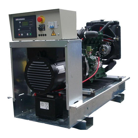
Where there are differences between An example of a generating set serial the nameplates, the generating-set number is: name plate data should be used. 11 12345 G LPW4 22 6 1. Alpha series LWA/LWX generating sets: acoustic set (left) and open set (right). - Page 6 ALPHA SERIES LWA/LWX GENSET OPERATORS' HANDBOOK alpha series lWa/lWX genset operators' handbook 1.2. The ISO 8999 symbols used by Lister Petter 1.2. The ISO 8999 symbols used by Lister Petter Power Systems 1.2 SAFETY SYMBOLS WARNING 1.2 safety syMbols Warning...
- Page 7 1.5 preparing the battery Warning If batteries are supplied they can be Untrained people must not start or supplied 'wet' or dry-charged. Wet operate any diesel gener a ting set. batteries need to be charged. Dry- It is dangerous.
- Page 8 Warning must be charged. Never allow battery cells to become short-circuited by metal objects. Charging a battery Severe burns and electric shock 1. Use a charge rate of approximately can result.
-
Page 9: The Control Module
2. the Control Module 2.1 the Control Module Figure 2.1 Typical Control Module The control module is used to start and It monitors various engine and stop the engine, either manually or generator parameters. Under out... - Page 10 2.2 Controls and indiCators Figure 2.1 Electric Start Control Module Figure 2.2 Typical AMF Control Module...
- Page 11 The LED display shows the selected parameter code and function as indicated by the icon. Code Function Automatic mode selection Manual mode selection Start under manual control Stop/Reset - this will clear any alarm condition or stop the engine if it is running...
- Page 12 • Generator kVA position 1 being the most recent. On • Generator Power Factor moving from the instrumentation to • Generator Load (kVAr) the event log the unit will display the • Generator Load (kWh, kVAh, kVArh) most recent entry.
- Page 13 Manual This mode allows manual control of the generator functions. Once in Manual mode the module will respond to the start button, start the engine, and run off load. If the engine is running off-load in the Manual mode and a remote start...
- Page 14 2.5 Module display The display is segmented into areas for instrumentation, units, alarm icons and various other icons. Inst. Icon Instrumentation Units Alarm Icon Active Instrumentation Units config Mode event Icon Instrumentation Units index 2.5.1 display example...
- Page 15 2.5.3 auto run icon When the engine is running in AUTO mode, an icon is displayed to indicate the reason for the set being run. Auto Run Reason Icon Remote Start Input ► Low battery run...
- Page 16 2.6 proteCtions will display the appropriate icon. If a When an alarm is present the LCD shutdown then occurs, the module display will jump from the ‘Information will again display the appropriate icon, page’ to display the Alarm Page. In flashing.
- Page 17 The module detects that the engine oil pressure has Low Oil Pressure Warning fallen below the low oil pressure pre-alarm setting level after the Safety On timer has expired. The module detects that the fuel level is below the Low Fuel Level configured setting.
- Page 18 Low Oil Pressure The engine oil pressure has fallen below the low oil pressure Shutdown trip setting level after the Safety On timer has expired. The module detects that the fuel level is below the configured Low Fuel Level setting.
-
Page 19: The Control System
ALPHA SERIES LWA/LWX GENSET OPERATORS' HANDBOOK ALPHA SERIES LWA/LWX GENSET OPERATORS' HANDBOOK alpha series lWa/lWX genset operators' handbook 3. THE CONTROL SYSTEM 3. THE CONTROL SYSTEM 3. the Control systeM CONTROL MODULE EMERGENCY STOP BUTTON AC CIRCUIT BREAKER CONTROL MODULE... - Page 20 3.2 the Control Module • DC circuit breaker • 2-, 3- or 4-pole AC circuit breaker The control module is used to start • AC instrumentation protection fuses and stop the engine, either manually •...
-
Page 21: Standard Electric Start Sets
4. standard eleCtriC start sets 4.1 features on the control module. An LED indicator by the side of the button Standard electric start sets have the will illuminate. following features: 4.Press the start button on the control •... - Page 22 4.3.4 alarm and fault 4.When the set is ready, the generator available LED illuminates and the Conditions 12V DC signal becomes available at During the running period the engine B7 and B8. At this point the load can con trol module monitors the set for the be connected to the generating set.
-
Page 23: Automatic Mains Failure Sets
5. autoMatiC Mains failure sets 5.1 features Operation of the emergency stop button will initiate controlled Automatic Mains Failure (AMF) sets shutdown. have the following features: Any attempt to restart the set will be •... - Page 24 5.2.3 Mains (utility) returns On LPWT4 sets there will be a ten- second preheat period. The generating The mains (utility) supply must remain set will then start and run up to speed healthy for five minutes before the load and voltage.
-
Page 25: Dummy Load
6. duMMy load The Dummy load comprises of a when the dummy load is required. If the number of resistive elements, to load level is below the 'trip' setting for suit the configuration of the genset,... -
Page 26: Long Run Sets
ALPHA SERIES LWA/LWX GENSET OPERATORS' HANDBOOK 7. long run sets 7. LONG RUN SETS 726 EXHAUST UEL FILTER 7 AIR CLEANER FUEL CONTROL RADIATOR SOLENOID LUB OIL EXPANSION BOTTLE AUXILIARY FILTER CUBICLE (E ECTRIC START O ENSET) - Page 27 7.2.6 Petter Power Systems will come as standard with 20 litres of running oil. Once the engine has obtained operating If the set arrives without this oil then the speed apply 75% load and run for following oil is recommended;...
-
Page 28: Routine Maintenance
8. routine MaintenanCe 8.2 diesel engine Warning Refer to the engine operators' Only qualified engineers should handbook, P027-08270, supplied a t t e m p t a n y m a i n t e n a n c e o r with the set, for details of routine adjustments. -
Page 29: Replacement Parts
10. replaCeMent parts 10.1 sourCe of supply 10.3 alternator parts When purchasing parts or giving Consult Lister Petter Power Systems instructions for repairs users should, (see 10.5). in their own interests, always specify genuine parts and quote the part 10.4 Cubicle parts... -
Page 30: Appendix 1 Installation And Commissioning
1 installation and CoMMissioning expelled from the building, otherwise site installation the engine can become damaged Warning due to overheating. All installation work should be 6.Exhaust fumes are dangerous. under taken by a competent pro- Ensure that the fumes are safely fessional engineer. - Page 31 1.It is the responsibility of the installer oil (see the engine operators' handbook). to ensure that the generating set is adequately earthed to a low- 3.Ensure that the battery connections resistance earthing rod or earth are secure.
-
Page 32: Appendix 2. List Of Drawings
2: list of draWings electric start sets LPW/LWX 2,3,4 (open) ............... 084-27396 LPW/LWX 2,3,4 (acoustic) ..............084-27397 LPW/LWX 2,3,4 + dummy load (open) ..........084-27398 LPW/LWX 2,3,4 + dummy load (acoustic) ........... 084-27399 LPW/LWX 2,3,4 + battery charger (open) .......... - Page 33 LPWT4/LPWXT4 (open) ..............084-27416 LPWT4/LPWXT4 (acoustic) ..............084-27417 LPWT4/LPWXT4 + dummy load (open) ..........084-27418 LPWT4/LPWXT4 + dummy load (acoustic) ......... 084-27419 LPWS/T (open) ................... 084-27428 LPWS/T (acoustic) ................084-27429 LPWS/T + dummy load (open) ............084-27430...
- Page 36 California to cause cancer, birth defects, and other reproductive harm. ALPHA LWA/LWX GENERATING SET OPERATORS' HANDBOOK, P027-10623, EDITION 3, OCTOBER 2017 © LISTER PETTER POWER SYSTEMS Head Office LISTER PETTER POWER SySTEMS LIMITED Unit 14 Estuary Court, Broadmeadow Industrial Estate...
Need help?
Do you have a question about the alpha Series and is the answer not in the manual?
Questions and answers