Table of Contents
Advertisement
Advertisement
Table of Contents

Related Manuals for WattBox 800 Series


Summary of Contents for WattBox 800 Series
- Page 1 ™ WB-800-IPVM-12 WB-800-IPVM-12 POWER CONTROLLED 1 CONTROLLED 2 CONTROLLED 3 CONTROLLED 4 CONTROLLED 5 CONTROLLED 6 RESET SAFE VOLTAGE UPS LINK NETWORK CONTROLLED 7 CONTROLLED 8 CONTROLLED 9 CONTROLLED 10 CONTROLLED 11 CONTROLLED 12 120VAC 60Hz QUICK START GUIDE...
-
Page 2: Front Panel
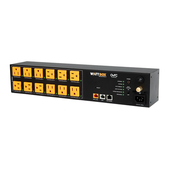
FRONT PANEL WB-800-IPVM-12 POWER CONTROLLED 1 CONTROLLED 2 CONTROLLED 3 CONTROLLED 4 CONTROLLED 5 CONTROLLED 6 RESET SAFE VOLTAGE UPS LINK NETWORK CONTROLLED 7 CONTROLLED 8 CONTROLLED 9 CONTROLLED 10 CONTROLLED 11 CONTROLLED 12 120VAC 60Hz A. Controllable outlets 1-12 – All outlets are switchable (IP controlled). B. -
Page 3: Rear Panel
UPS link port – For connection to a WattBox UPS unit. ACC port – Accessory port for future use. This WattBox is not compatible with WB-600-FP. K. Network port – Connect to the local area network (LAN) for IP control and monitoring. -
Page 4: Package Contents
The unit can also be mounted flush with the rack or set back to the most convenient position for a particular installation. Attach the brackets to the WattBox in the desired position using the supplied hardware, then install the WattBox into the rack using standard rack screws. - Page 5 Small bracket mounting Screw Position Screw Position Screw Position Wall Mounting Page 5...
- Page 6 Large bracket mounting USE CENTER HOLES FOR ANGLED MOUNTING USE CENTER HOLES FOR ANGLED MOUNTING USE CENTER HOLES FOR ANGLED MOUNTING Page 6...
-
Page 7: Wall-Mounting Options
WALL-MOUNTING OPTIONS The WattBox 800 Series can be mounted to a wall or cabinet by using the small bracket. Mount the small bracket to the WB-800 with the flat part of the bracket facing away from the outlets. 1. Locate wall studs using a stud finder (not included). -
Page 8: Connections And Setup
CONNECTIONS AND SETUP 1. If attaching a WattBox UPS battery pack to the power conditioner, connect an Ethernet cable between the UPS Link ports on the power conditioner and the UPS. 2. For IP control and OvrC connectivity, connect a network cable from your router or switch into the WB-800 Network port. -
Page 9: Logging Into The Web Interface
LOGGING IN TO THE WEB INTERFACE You need to enter the username and password to access the WattBox’s web interface. The default entries are below; you must change the username and the password after logging in for the first time (and record the new credentials below). -
Page 10: Led Indicators
Surge Green The WattBox is powered on and outlets are protected. Protected The WattBox is not powered on, or the MOVs have opened, removing power from the outlets. Grounded Green Incoming AC outlet is grounded. Incoming AC outlet is NOT grounded and requires inspection by an electrician. -
Page 11: Troubleshooting
If the circuit breaker continues to trip, move one or more components to another WattBox. The attached Component is plugged into a controlled outlet To turn the outlet on, log in to the WattBox interface or press component is and the outlet is off. the power button. -
Page 12: Important Safety Instructions
Caution – Potential injury Do not use this product with extension cords, multioutlet power strips, multioutlet extenders, or UPS devices (other than a WattBox UPS). The power capacity of these accessories can be overloaded by this product and may result in a risk of fire, or property damage. - Page 13 Warning – Liquid: avoiding electrical shocks Do not operate the WattBox if liquid of any kind is spilled onto or inside the unit. Do not operate it near rain or water, even water that is contained (for example, bathtub or sink).
-
Page 14: Fcc Warning
Caution – Exposure to heat Do not expose the WattBox to direct sunlight or place it near wall heaters, space heaters, or in an enclosed space prone to temperature increase. Do not use the device in a confined, poorly-ventilated location; this can overheat the unit, possibly even causing a fire. If used in a small space other than an EIA-standard rack, ensure that there is adequate space around the device. - Page 15 nearby radio and television reception. It is essential that only the supplied power cord by used. (2) Use only shielded cables to connect I/O devices to this equipment. Note: THE MANUFACTURER IS NOT RESPONSIBLE FOR ANY RADIO OR TV INTERFERENCE CAUSED BY UNAUTHORIZED MODIFICATIONS TO THIS EQUIPMENT.
-
Page 16: Warranty
WARRANTY 3-Year Limited Warranty This SnapAV® product has a 3-Year Limited Product Warranty and a 3-Year Network Connectivity Warranty. The 3-Year Limited Product Warranty includes parts and labor repairs on all components found to be defective in material or workmanship under normal conditions of use. - Page 17 telephone, or lightning surge while connected to a properly installed SnapAV surge protector. SnapAV must determine that the surge protector shows signs of surge damage or is operating outside of design specifications, relative to its surge protection capability, and under all of the circumstances failed to protect your connected equipment. This policy is subject to the conditions below: Proof of purchase required SnapAV’s connected equipment policy extends to the original purchaser of the SnapAV product only and is non-transferable.
- Page 18 WARNING This product can expose you to chemicals including carbon black, which is known to the State of California to cause cancer. For more information, go to www.P65Warnings.ca.gov. Version 200401-1030 MS Page 18...
- Page 19 Page 19...
- Page 20 Page 20...
Need help?
Do you have a question about the 800 Series and is the answer not in the manual?
Questions and answers