
Related Manuals for KSB PumpDrive


Summary of Contents for KSB PumpDrive
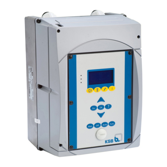
- Page 1 Self-cooling Motor-independent Frequency Inverter PumpDrive Installation/Operating Manual...
- Page 2 All rights reserved. The contents provided herein must neither be distributed, copied, reproduced, edited or processed for any other purpose, nor otherwise transmitted, published or made available to a third party without the manufacturer's express written consent. Subject to technical modification without prior notice. © KSB Aktiengesellschaft, Frankenthal 01.10.2015...
-
Page 3: Table Of Contents
Sizes ......................... 17 Dimensions and weights ................18 Mounting options ................... 18 Installation at Site ................19 Safety regulations ................... 19 Checks to be carried out prior to installation ..........19 Mounting PumpDrive ..................19 Electrical connection ..................20 PumpDrive 3 of 162... - Page 4 Faults/Malfunctions: Trouble-shooting ............131 11.2 Warnings ....................... 132 11.3 Alerts ......................134 Purchase Order Specifications ............138 12.1 Ordering spare parts ..................138 12.2 Accessories ....................138 Commissioning report ..............157 EC Declaration of Conformity ............158 Index ....................159 PumpDrive 4 of 162...
-
Page 5: Glossary
PumpDrives. The KSB local bus cannot be used for external communication. Abbreviation for "residual current device" Pump Machine without drive, additional components... -
Page 6: General
The serial number uniquely describes the product and is used as identification in all further business processes. In the event of damage, immediately contact your nearest KSB service centre to maintain the right to claim under warranty. 1.2 Target group This operating manual is aimed at the target group of trained and qualified specialist technical personnel. -
Page 7: Safety
The product must not be used in potentially explosive atmospheres. PumpDrive 7 of 162... -
Page 8: Personnel Qualification And Training
▪ Carry out work on the product during standstill only. ▪ As soon as the work has been completed, re-install and/or re-activate any safety- relevant and protective devices. Before returning the product to service, observe all instructions on commissioning. PumpDrive 8 of 162... -
Page 9: Unauthorised Modes Of Operation
The software has been specially created for this product and thoroughly tested. It is impermissible to make any changes or additions to the software or parts of the software. Software updates supplied by KSB are excluded from this rule. 2.11 Electromagnetic compatibility The EMC Directive sets out the requirements concerning the interference immunity and the RFI emissions of electrical equipment. -
Page 10: Transport/Temporary Storage/Disposal
On transfer of goods, check each packaging unit for damage. In the event of in-transit damage, assess the exact damage, document it and notify KSB or the supplying dealer (as applicable) and the insurer about the damage in writing immediately. - Page 11 3 Transport/Temporary Storage/Disposal Fig. 2: Transporting a horizontal pump set Fig. 3: Transporting a vertical pump set PumpDrive 11 of 162...
-
Page 12: Storage
- Line chokes with copper windings - Copper lines for internal wiring Dispose of materials in accordance with local regulations or in another controlled manner. PCBs, power electronics, capacitors and electronic components are all special waste. PumpDrive 12 of 162... -
Page 13: Description
✘ ✘ Open-loop control mode via setpoint specification ✘ ✘ User-definable speed (0 to 70 Hz for PumpDrive, 0 - 140 Hz for PumpDrive S) ✘ ✘ Sleep mode See type series booklet for detailed description of designation. Based on monitoring of the effective motor power Based on the current flow rate (measured or estimated). - Page 14 Open-loop control ✘ ✘ ✘ Open-loop control mode via setpoint specification ✘ ✘ ✘ User-definable speed (0 to 70 Hz for PumpDrive, 0 - 140 Hz for PumpDrive S) ✘ ✘ Sleep mode ✘ ✘ ✘ Programmable start and stop ramps See accessories: DPM (only in conjunction with the standard control panel) Accessories are included in the scope of supply but not fitted.
-
Page 15: Technical Data
Range: 1 - 8kHz, in 0.5 kHz steps Sizes A and B: 4 kHz Sizes C and D: 2.5 kHz 5000 V/µs max. (depending on the PumpDrive size) Phase rate of rise, dv/dt See accessories: DPM (only in conjunction with the standard control panel) Accessories are included in the scope of supply but not fitted. - Page 16 The values are for orientation purposes only. The value refers to the nominal duty point (50 Hz) only. Also see the pump's noise characteristics. They, too, are documented for nominal duty operation. Other values may occur during variable speed operation. to EN 60068-2-64:1994 PumpDrive 16 of 162...
-
Page 17: Power Range
11 ... 22 kW 30 ... 45 kW Fig. 5: Sizes PWM carrier frequency at a max. ambient temperature of 40 °C: - Sizes A and B: 4 k Hz - Sizes C and D: 2.5 kHz PumpDrive 17 of 162... -
Page 18: Dimensions And Weights
600 450 290 125 410 573 659 450 300 125 410 635 M10x9 (4x) ..037K00.. 37 ..045K00.. 45 4.9 Mounting options Motor mounting Wall mounting Control cabinet mounting The dimensions provided refer to PumpDrive, including the wall mounting brackets. PumpDrive 18 of 162... -
Page 19: Installation At Site
With power derating 0 °C to +50 °C The service life of PumpDrive is reduced if an average temperature of +35 °C/24 h is exceeded or if PumpDrive is operated at temperatures below 0 °C or above +40 °C. In addition, the power rating is reduced. -
Page 20: Electrical Connection
Installation kits for subsequent conversion to the wall mounting configuration for existing pump systems are available from KSB. PumpDrive should rest flush against the wall so that the air flow of the fans is directed through the heat sink. - Page 21 The power cables must be designed with a cross-section suitable for the nominal mains current. If a contactor is used in the power cable (upstream of PumpDrive), this must be configured for an AC1 duty rating; the rated current values of the PumpDrives used are added and the result is increased by 15 percent.
- Page 22 97,7 Length of motor connection cable If PumpDrive is not mounted on the motor to be controlled, longer motor connection cables may be required. The stray capacitance of the connection cables may result in high-frequency discharge currents flowing to ground. The sum of the discharge current and motor current may exceed the output-side rated current of PumpDrive.
- Page 23 PumpDrive and the motor to be controlled. These filters reduce the voltage ramp-up time of the PumpDrive output voltages and limit their peaks. 5.4.2.2 Electrical protection equipment Provide three fast-acting fuses in the mains power supply line to PumpDrive.
- Page 24 The shield for the control cable (connection on PumpDrive side only) also serves as protection against radiated emission. If you are using shielded cables to improve interference immunity, also use a wide contact face for the different earth connections.
- Page 25 ▷ Never remove the upper housing part from the heat sink. ▷ Mind the capacitor discharge time. After switching off PumpDrive, wait five minutes until dangerous voltages have discharged. The housing cover comprises a V-shaped cover for the power and motor connection cable connections and an L-shaped cover for the control cable connection.
- Page 26 Connect the line for a PTC connection/PTC thermistor to terminal strips 5/6. If the sensor signal is transmitted to PumpDrive from a higher-level control system or a PLC, make sure that all the signals are electrically isolated.
- Page 27 Short circuit of motor winding and PTC connection/ PTC thermistor Risk of fatal injury due to electric shock! ▷ De-energise PumpDrive before opening the housing or when working on the terminals of the inputs and outputs. Sizes A and B Fig.
- Page 28 Connect the cores for a PTC connection/PTC thermistor to terminal strips 5/6. If no (PTC/PTC thermistor) PTC connection is available on the motor end, parameter 3-3-5-1 must be deactivated. Connecting the sensors Terminal 1-4: Alternative connection of an analog input AIN2 (⇨ Section 5.4.3.6 Page PumpDrive 28 of 162...
- Page 29 5 Installation at Site 5.4.3.3.1 Mounting ferrite cores Depending on the size of PumpDrive, 1 to 3 ferrite cores must be mounted to the PumpDrive power cable in order to meet the requirements of the relevant EMC Directive or product standard in conjunction with KSB/Siemens or KSB SuPremE motors.
- Page 30 The line input currents may vary depending on the actual line impedance. In low- impedance mains, higher currents may occur. To limit the line input current, external line chokes can be used alongside the line chokes already integrated in PumpDrive (in the power range up to and including 45 kW).
- Page 31 ▪ Only connect or remove the field bus module when it is de-energised. ▪ Always attach the field bus module to the lower P8 slot on the PumpDrive. (⇨ Section 5.4.3.6 Page 31) ▪ The procedure for installing the field bus modules is identical for all types (LON, Profibus, Modbus).
- Page 32 Ground for +24 V DIG IN6 Digital input (15/28 V DC) DIB-IN5 Digital input (15/28 V DC) DIG-IN4 Digital input (15/28 V DC) Impairment of protection provided by enclosure when cable diameters other than those specified are used. PumpDrive 32 of 162...
- Page 33 The ground at terminal P7:7 can also be used to connect an analog ground. AGND and GNG have the same potential. Analog signals from a higher-level control station must be electrically isolated when they are transmitted to PumpDrive, for example by using isolating amplifiers.
- Page 34 Fig. 18: Connecting cable ends Mini USB connection Supply voltage Connect the red line (24 V) to terminal strip P4 (terminal P4:13) of PumpDrive. Connect the black line (GND) to terminal strip P4 (terminal P4:20) of PumpDrive. PumpDrive 34 of 162...
- Page 35 Mounting the graphical control panel No lines need to be connected when installing the graphical control panel; the connection between the display and PumpDrive is established using a plug-type connector. The plug-type connector is automatically connected when the display is mounted.
- Page 36 5 Installation at Site Remove the CPU module from slot 1. Rotate the CPU module 180° and connect it to slot 2. Rotate the control panel 180° and mount to PumpDrive. 5.4.3.8 Mounting the housing cover Control panel/blanking plate Position the control panel or blanking plate.
-
Page 37: Operation
Service interface PumpDrive configuration and parameterisation via PC/notebook. 6.1.1 LED traffic light function The LED traffic light function provides information about the current PumpDrive operating status. Table 23: LED description Description One or more than one alert is active One or more than one warning is active... - Page 38 Master PumpDrive Flashing green Aux. master PumpDrive No display PumpDrive in single-pump configuration Mode LED The mode LED shows the current operating mode of PumpDrive: Table 27: Mode LED states Function of PumpDrive OFF mode, switched off Amber Automatic mode...
- Page 39 OFF or Auto Stop state. If PumpDrive is in the Auto Run state before the key is pressed, it continues to operate with the current speed. Setting the speed (⇨ section 6.1.5, page 40) "Func"...
-
Page 40: Graphical Control Panel
Description Function LED traffic light The traffic light function provides information function about the system's operating status. Graphical display Information about PumpDrive operation is displayed. Navigation keys Navigation and parameter setting Operating keys Toggling operating modes Service interface PumpDrive configuration and parameterisation... - Page 41 6 Operation 6.2.1 LED traffic light function The LED traffic light function provides information about the current PumpDrive operating status. Table 31: LED description Description One or more than one alert is active One or more than one warning is active...
- Page 42 Starts PumpDrive in manual operating mode Stops PumpDrive Switches to automatic mode Auto Parameterisable function key Func Manual mode via control panel NOTE After a power failure, PumpDrive reverts to OFF mode and manual mode must be restarted. PumpDrive 42 of 162...
- Page 43 Table 35: Assignment of function keys for manual mode and graphical control panel Menu When the MAN key is pressed in the OFF or Auto Stop state: PumpDrive is operated at the lower motor frequency limit value (3-6-1-2) . When the MAN key is pressed in the Auto Run state: PumpDrive assumes the current operating speed.
- Page 44 Settings menu. 6.2.5.1.1 Defining operating parameters in the start menu The start menu appears on the PumpDrive display following the boot procedure. Up to 20 operating parameters can be defined in the start menu via parameter (3-1-3-1) .
- Page 45 Menu: Diagnosis In the Diagnosis section, the user is provided with information about faults and warnings that pertain to the pump set or process. PumpDrive can be in fault (standstill) or warning (operational) status. The user can also find previous messages in the history.
- Page 46 English language French English Italian 6.2.5.3.2 Access levels Four access levels have been defined to prevent accidental or unauthorised access to PumpDrive parameters: Table 42: Access levels Access level Description Standard (No Login) Access without password entry. Customer Access level for the expert user with access to all parameters required for commissioning.
- Page 47 ⇨ The bar above the entry displays the value currently input. Use the arrow keys to increase or decrease the value displayed. Confirm the selected value by pressing OK. ⇨ The cursor moves to the next position (second position from the left). PumpDrive 47 of 162...
-
Page 48: Service Interface
Make the settings as described for the subsequent items. Press the OK key to save the new parameter value. 6.2.5.4 Menu: Information All direct information about PumpDrive is provided in the Information section. Important details regarding the firmware version are listed here. 6.3 Service interface CAUTION... -
Page 49: Commissioning/Shutdown
▪ No voltage is applied to the power supply module of PumpDrive. ▪ PumpDrive or the pump set must not be loaded above the permissible nominal power. ▪ If PumpDrive is going to be used in multiple pump operation, note (⇨ Section 7.1.3 Page 62) prior to commissioning. 7.1 Pump operation 7.1.1... - Page 50 Frequency Low setting range for the setpoint is 50 - 100 % (e.g. 5 - 10 V, 12 - 20 mA). If a setpoint below 50 % is specified, PumpDrive always operates at its minimum frequency of 25 Hz (50 %).
- Page 51 7.1.1.3 Open-loop control mode In open-loop control mode, PumpDrive translates the specified setpoint into the corresponding motor speed. The process controller is deactivated. PumpDrive starts up in automatic mode if digital input 1 is supplied with +24 V DC (terminal strip P4:13/14).
- Page 52 3-6-1-2 : 50 %) set in PumpDrive always operates at a minimum frequency of 25 Hz ( the factory. If the setting range of the setpoint signal is to apply from the minimum frequency ( 3-6-1-2 ) on, the AnIn 1 Low parameter ( 3-8-2-7 ) has to be set to 50 % and the corresponding unit.
- Page 53 Bus Enable parameter specifications have to be taken from the relevant product literature of the bus modules, but are matched with the basic settings of PumpDrive. 7.1.1.3.4 Open-loop control mode using a digital potentiometer (key function) This function can be activated for single-pump operation at any time as soon as the parameterised digital inputs are connected.
- Page 54 Current changes in consumption are identified by comparison with the setpoint and then compensated by adjusting the speed. PumpDrive has been set at the factory so that it will automatically recognise a sensor connected to analog input 2 and will then automatically activate closed-loop control mode in the following cases: ▪...
- Page 55 7 Commissioning/shutdown PumpDrive Process controller Speed controller ∆ ∆p ∆n U[V,f] ∆ actual p setpoint Controlled system (PI controller) (PI controller) ∆ actual Fig. 28: Closed-loop control mode block diagram 4 5 6 7 8 Sensor 4...20mA Fig. 29: Terminal wiring diagram, closed-loop control mode (dashed line = optional)
- Page 56 10 AGND P7). Analog input 2 is configured for connecting an actual value signal (4 - 20 mA) by default. If such an actual value signal (4 - 20 mA) is connected, PumpDrive detects it as a sensor signal and, following a restart (system reboot), automatically (PI...
- Page 57 (3-9-1-5) is defaulted to Variable Pressure at the factory. If a different controller type is required, change the selection to suit requirements. The Variable Pressure process type activates the dynamic pressure setpoint compensation function (⇨ Section 7.2.4.1 Page 85) . PumpDrive 57 of 162...
- Page 58 ▪ Low value selected for PI P Prop Gain (3-9-1-2) : Moderate controller response speed and small overshoot ▪ Large value selected for PI P Prop Gain (3-9-1-2) : Faster controller response and larger overshoot PumpDrive 58 of 162...
- Page 59 PumpDrive is to control the system to achieve a setpoint of 6.7 bar in a differential pressure control process. For this purpose, a differential pressure sensor (4 - 20 mA) with a measuring range of 0 to 10 bar is connected to analog input 2 of PumpDrive. The setpoint is specified using the control panel.
- Page 60 For this purpose, a differential pressure sensor (4 - 20 mA) with a measuring range of 0 to 10 bar is connected to analog input 2 of PumpDrive. The setpoint is specified using an external setpoint signal (4 - 20 mA) via analog input 1.
- Page 61 The dual pump module (DPM) is available as a separate accessory/spare part. The dual pump module can only be used in combination with the standard control panel for the PumpDrive Basic model. It cannot be used in combination with the blanking plate or the graphical control panel.
- Page 62 The motor parameters must be set prior to commissioning. (⇨ Section 7.1.1.1 Page Up to six PumpDrives can be operated in parallel in a multiple pump configuration. The defined master (PumpDrive Advanced) controls the slave PumpDrives (PumpDrive Basic) to ensure that they are utilised optimally. If the master fails or malfunctions, one of the other PumpDrives (Advanced) can assume the role of master.
- Page 63 Digital input 1: Enables the respective PumpDrive. If digital input 1 is not connected to 24 V, the relevant PumpDrive in a multiple pump configuration will not be used as an active frequency inverter, i.e. this device will not be activated.
- Page 64 (3-1-1-4) displays the IDs of all the PumpDrives connected to the KSB local parameter bus. On the auxiliary master or the Basic control panel, only the ID of the PumpDrive equipped with the Advanced control panel is shown under this parameter.
- Page 65 PumpDrive to which the control panel is connected. At the beginning of parameterisation, 0 is displayed for all the PumpDrive IDs, as no PumpDrive IDs have been assigned yet. When a PumpDrive is selected, its LED flashes. This allows you to identify the PumpDrive to which the active master control panel is connected.
- Page 66 Fig. 39: Characteristic curves for defining the start and stop limits in multiple pump configurations (permissible area is shaded) The following parameters have to be entered for the main pump only. If PumpDrive is supplied on its own, the factory settings are suitable for operation of a 4-pole...
- Page 67 2.5 s 3-12-5-1 Maximum number of pumps running simultaneously 3-12-5-5 Pump changeover Enabled Parameterise PumpDrive 3 using the active master control panel of PumpDrive 1: Table 64: Configuration example for multiple pump operation: PumpDrive 3 Parameter Description Value 3-1-1-4 Selection of a PumpDrive from the multiple pump configuration...
- Page 68 For this purpose, the drives are interconnected by means of the KSB local bus. Multiple pump configurations enable demand-based closed-loop control of the PumpDrives connected to the KSB local bus. Pumps of the same type and same power rating can be started in parallel and stopped depending on the motor input power.
- Page 69 In multiple pump configurations, the PumpDrives must be connected via an internal KSB local bus. The active master control panel then controls all other connected PumpDrives via the KSB local bus. The maximum number of PumpDrives in a multiple pump configuration is limited to six.
- Page 70 Fig. 40: KSB local bus wiring for master/auxiliary master/slave mode (1 main pump, 1 auxiliary pump, 1 slave pump) The KSB local bus in the first and last PumpDrive must be terminated via a resistor. This is implemented by means of a wire jumper between terminals 1 and 2 on terminal strip P4.
- Page 71 PumpDrives to ensure that it is supplied with voltage in the event that the main pump fails. If the sensor signal is transmitted to PumpDrive from a higher-level control system or a PLC, make sure that all the signals are electrically isolated.
-
Page 72: Application Functions
Fig. 41: Connection example for master/AUX master operation: a) 3-wire sensor, b) 2- wire sensor 7.2 Application functions 7.2.1 PumpDrive protective functions If the Advanced control panel fails, the Advanced protective functions can no longer be ensured. The Advanced protective functions are identified as such in the following. - Page 73 7.2.1.2 Electrical motor protection by overvoltage/undervoltage monitoring PumpDrive monitors the mains voltage. If it falls below 380 V -10 % or exceeds 480 V +10 %, this results in tripping and an alert message is output. The alert must be acknowledged before the drive can be restarted.
- Page 74 In closed-loop control mode, the suppressed frequency should lie outside the PumpDrive's correction frequency range. Otherwise sudden PumpDrive speed changes can lead to pressure fluctuations. First the upper limit to prevent resonant frequencies Hi Bypass Freq 3-3-7-2 ) and then the lower limit to prevent resonant frequencies Lo Bypass Freq 3-3-7-1 ) have to be entered.
- Page 75 Auto. The data required for tripping in the event of dry running or hydraulic blockages must be "taught" to PumpDrive at minimum load for the system it is installed in. To 3-12-2-1 . You then have to confirm by...
- Page 76 If PumpDrive is not pre-configured at the factory, the pump characteristic curve is defined for PumpDrive using 6 Q, H, and P data points. The following illustration shows the parameters of the respective data points using a pump characteristic curve as an example.
- Page 77 Parameterisation of the 7 power requirement points P0, P1, ... P6 for Q0, Q1, ... Q6 The following parameters have to be set to match PumpDrive to the driven pump. Refer to the pump product literature for the values to be set.
- Page 78 For parameterising the pump characteristic curve/flow rate estimation (⇨ Section 7.2.2.1 Page 76) and (⇨ Section 7.2.2.3.1 Page 80) If impermissible operating conditions are detected, PumpDrive can, after a specified time delay, respond either with a warning or by tripping (Stop&Trip) or not respond at all.
- Page 79 Q Hi Timeout Time 0..120 (s) 20 s 3-12-4-3 Q High flow timeout No Function No Function function Warning Stop and Trip 3-12-4-4 Q Low flow limit 0 to 9999 in physical unit for 3-2-2-2 Q 100 m³h Unit PumpDrive 79 of 162...
- Page 80 7.2.2.3.1 Flow rate estimation (for PumpDrive Advanced only) The Flow Rate Estimation function allows the estimated flow rate of the pump to be displayed directly in the PumpDrive menu without the need to connect a flow rate sensor. Display of flow rate...
- Page 81 2. The maximum flow rate as per the pump characteristic curve (Q 100 % = ) is 24.5 m Table 78: Parameter(s) for flow rate estimation via a differential pressure sensor Parameter Description Settings Factory setting 3-2-2-1 Setpoint unit 3-2-2-2 Q unit m³/h m³/h PumpDrive 81 of 162...
- Page 82 In multiple pump configurations, the digital inputs, relay outputs and analog outputs configuration must be parameterised individually for each PumpDrive. Activation of the warnings for the analog inputs has to be enabled separately for the main pump and any redundant auxiliary main pump. Limits and time delays for the analog inputs have an identical value for all the PumpDrives in the system and, therefore, have to be exclusively set via the active master control panel.
- Page 83 Parameter Description Possible settings Factory setting 3-6-3-1 Lower limit Analog IN 1 Low (3-8-2-7) to Analog IN (3-8-2-8) in Analog IN 1 Unit 1 High Analog input 1 (3-8-2-6) 3-6-3-2 Upper limit for analog input 1 PumpDrive 83 of 162...
- Page 84 (3-2-2-1) Setpoint monitoring 3-5-1-3 (3-5-1-2) to 9999 in Upper limit Minimum Setpoint (3-2-2-1) physical setpoint unit Setpoint monitoring 3-2-2-1 Physical unit of setpoint Selection list III (⇨ Section 10.1 Page 129) Access: Service PumpDrive 84 of 162...
- Page 85 (3-4-2-1) [%] [3-2-2-1] PumpDrive must be supplied with the signal of a pressure or differential pressure sensor and the current flow rate as reference input variables for the dynamic pressure setpoint compensation function. The method used for determining the flow rate for setpoint compensation depends on the PumpDrive model (Basic/Advanced) and its parameterisation.
- Page 86 7 Commissioning/shutdown Table 85: Parameters for the dynamic pressure setpoint compensation function on a PumpDrive Basic model using flow rate estimation based on the speed Parameter Description Possible settings Factory setting 3-2-2-1 Physical unit of setpoint Selection list III (⇨ Section 10.1 Page...
- Page 87 PumpDrive Advanced model using flow rate estimation based on the speed or the power: Table 89: Parameters for the dynamic pressure setpoint compensation function on a PumpDrive Advanced model using flow rate estimation based on the speed...
- Page 88 AI 1 descriptor Pressure P1 3-8-3-11 AI 1 descriptor Pressure P2 The parameters for parameterisation of the dynamic pressure compensation function on a PumpDrive Basic model using flow rate measurement via a sensor must be set as follows: PumpDrive 88 of 162...
- Page 89 7 Commissioning/shutdown NOTE 3-8-2-11 and 3-8-3-11 must not both be set to "Q" at the same time. Parameters Table 96: Parameter(s) for dynamic pressure compensation function on a PumpDrive Advanced model using flow rate measurement via a sensor Parameter Description...
- Page 90 (5)), PumpDrive increases the setpoint by a value of (3) (test pulse) for a period of time (2). If the flow rate is zero, this pressure compensation will continue to be applied.
- Page 91 (⇨ Section 7.2.5 Page 90) , the drive will respond as follows: ▪ If none of the digital inputs (configured for fixed speed) is connected, PumpDrive will control pump operation in line with the given process variables.
- Page 92 0 Up to ramp 1/2 Up 3-3-6-7 3-11-4-1 Frequency to 0..100 (%) change from ramp 1/2 Down to ramp 0 3-5-3-4 3-11-4-1 Output frequency in 0..100 (%) manual mode 3-11-4-1 Maximum output 1..70 (Hz) frequency PumpDrive 92 of 162...
- Page 93 This can save a significant amount of energy in the medium speed range. If the values of all the data points are set to zero, PumpDrive operates with a linear V/f characteristic. By default, PumpDrive is set to a square V/f characteristic.
-
Page 94: Device Functions
PumpDrive. 7.4.1 Digital inputs PumpDrive is equipped with six digital inputs (24 V process level). Inputs 1 and 6 are assigned a fixed function: ▪ Digital input 1: Start/stop command for single-pump operation, enable in multiple pump configurations ▪... - Page 95 By changing the scaling, you can alter the setting range for the input signal by the required factor. 3-8-2-11 Description of Analog Process IN 1 Pressure P1 Pressure P2 Temperature Approximate time delay factor in unit [s] PumpDrive 95 of 162...
- Page 96 0,01..1 (s) time constant Multiple output values On the PumpDrive analog output, up to four different operating parameters (sources) can be output as voltage signals. If two digital inputs are assigned the function of a multiplexer, the source is output as a function of the logical wiring of the digital inputs.
- Page 97 100 ms (10 Hz). Table 107: Analog output sources Bit 1 Bit 0 Analog output source Source 1 24 V Source 2 24 V Source 3 24 V 24 V Source 4 PumpDrive 97 of 162...
-
Page 98: Maintenance/Inspection
After switching off PumpDrive, wait five minutes until dangerous voltages have discharged. NOTE All maintenance, service and installation work can be carried out by KSB Service or authorised workshops. Find your contact in the attached "Addresses" booklet or on the Internet at "www.ksb.com/contact". -
Page 99: Wiring Diagrams
9 Wiring diagrams 9 Wiring diagrams 9.1 Open-loop control mode Fig. 49: Connection example for open-loop control mode PumpDrive 99 of 162... -
Page 100: Closed-Loop Control Mode
9 Wiring diagrams 9.2 Closed-loop control mode Fig. 50: Connection example for closed-loop control mode PumpDrive 100 of 162... -
Page 101: Multiple Pump Configuration
9 Wiring diagrams 9.3 Multiple pump configuration Fig. 51: Connection example for multiple pump operation: PumpDrive 1 Master PumpDrive 101 of 162... - Page 102 9 Wiring diagrams Fig. 52: Connection example for multiple pump operation: PumpDrive 2 AuxMaster PumpDrive 102 of 162...
- Page 103 9 Wiring diagrams Fig. 53: Connection example for multiple pump operation: PumpDrive 4 Slave (jumper 1 - 2 on terminal strip P4 only if slave without control panel -> CAN bus terminator PumpDrive 103 of 162...
-
Page 104: Parameter Lists
Display of motor power rating in HP 1-2-1-3 Motor Voltage Display of motor voltage 1-2-1-4 Frequency Display of motor frequency 1-2-1-5 Motor Current Display of motor current 1-2-1-6 Speed [RPM] Display of speed in Signals Menu for signals PumpDrive 104 of 162... - Page 105 Analog IN 1 of actual value of analog input 1 1-3-2-3 Analog IN 2 Display of actual value of analog input 2 1-3-2-4 Analog OUT 1 Display of actual value of analog output Selection Is Inactive PumpDrive 105 of 162...
- Page 106 10 Parameter lists Parameter Description Factory Setting Unit Access level Possible settings setting Min. Max. PumpDrive PumpDrive menu 1-4-1 Status Submenu for displaying the current status of PumpDrive 1-4-1-1 DC Link Voltage Actual value of DC link voltage 1-4-1-2 Heat Sink Temp °C...
- Page 107 6 Diagnosis Main menu for diagnostics Alarm History Alert history 2-1-1 Alarm History Submenu for documentation of alerts 2-1-1-2 Alarm History Display of past alerts Warnings Menu for warnings 2-2-1 Warnings Submenu for displaying various warnings PumpDrive 107 of 162...
- Page 108 2-3-1-1 Alarm Display of current alerts Op Logger Menu for data logger 2-4-1 PumpDrive Submenu for PumpDrive data logger 2-4-1-1 PD Temp High Display of high temperatures in PumpDrive 2-4-1-2 Line Volt High Display of high mains voltage...
- Page 109 Auto 3-1-1-3 Backlight Time 1000 Customer Time interval of LC display lighting (Auto mode) 3-1-1-4 ID Selec PDrive Customer Display of identifier of PumpDrive selected 3-1-2 Set-up Submenu for settings 3-1-2-1 Set-up Version 1.01 99.99 Customer User-defined version number...
- Page 110 Access level Possible settings setting Min. Max. 3-1-5-1 PDrive -> HMI Customer Transfer parameter Start settings from PumpDrive to HMI 3-1-5-2 HMI -> PDrive Customer Transfer parameter Start settings from HMI to PumpDrive 3-1-5-3 Trip Reset Reset trip status of...
- Page 111 Server guard time 3-1-7-3 Backup Adv-HMI Customer Disabled Backup Advanced Enabled 3-1-7-4 Backup Guard Tm Customer Time value for identifying PumpDrive as the active master control panel PumpDrive PumpDrive menu 3-2-1 Basic Settings Submenu for displaying basic settings 3-2-1-1 MultiPump Role...
- Page 112 Customer Selection of nominal motor frequency 3-3-2-4 Rated Current Customer Selection of nominal motor current 3-3-2-5 Rated Speed 3600 Customer Selection of nominal motor speed 3-3-2-6 Rated Cosphi 0.99 Customer Selection of nominal motor cos phi PumpDrive 112 of 162...
- Page 113 Ramp 2 used to go from setpoint frequency to stop frequency 3-3-6-6 R1/2 Start Freq Customer Frequency to change from ramp 0 to ramp 1/2 3-3-6-7 R1/2 Stop Freq Customer Frequency to change from ramp 1/2 to ramp 0 PumpDrive 113 of 162...
- Page 114 Setpoint compensation for dynamic pressure compensation 3-4-3 Sleep Mode Submenu for sleep mode 3-4-3-1 Sleep Mode Customer Disabled Activate/deactivate Enabled sleep mode 3-4-3-2 Diff to Restart 9999 3-2-2-1 Customer Selection of feedback and setpoint to start PumpDrive 114 of 162...
- Page 115 3-5-2-2 Prset Setp Step 9999 3-2-2-1 Customer Increment/ decrement for setpoint frequency in manual mode 3-5-3 Prset OutFrq Fixed frequency submenu, selection via digital inputs 3-5-3-1 Preset OutFrq 1 Customer Fixed frequency, selection via digital inputs PumpDrive 115 of 162...
- Page 116 Frequency Lo 3-6-1-3 Customer Selection of lower limit value for motor frequency 3-6-1-3 Frequency Hi 3-6-1-2 Customer Selection of upper limit value for motor frequency 3-6-1-4 MotMod Curr Lim Customer Selection of motor mode current limit PumpDrive 116 of 162...
- Page 117 Selection of upper limit value for analog input monitoring 3-6-3-3 An IN1 Wrn Customer Time delay for TDly function 3-6-3-4 An IN 1 Wrn Fnc Customer No Function Analog input Warning monitoring function Stop & Trip PumpDrive 117 of 162...
- Page 118 Low Load Fnc Customer No Function Selection of low Warning load functions Stop & Trip 3-6-5 Setpoint Warns Submenu for setpoint monitoring 3-6-5-1 Min Setpoint 3-5-1-3 3-2-2-1 Customer Selection of low limit value for setpoint monitoring PumpDrive 118 of 162...
- Page 119 Page 129) input 5 3-7-2 Digital OUT 1 Submenu for display of digital output 1 3-7-2-1 Dig OUT 1 Fnc Customer Selection list II Selection of (⇨ Section 10.1 function of digital Page 129) output 2 PumpDrive 119 of 162...
- Page 120 AI1 Lo Current 3-8-2-5 Customer Analog IN 1 Low current 3-8-2-5 AI1 Hi Current 3-8-2-4 Customer Analog IN 1 High current 3-8-2-6 AI1 Unit Customer Selection list III Unit of Analog IN 1 (⇨ Section 10.1 Page 129) PumpDrive 120 of 162...
- Page 121 Analog IN 1 3-8-3-10 AI2 Scaling Customer Analog IN 2 Scaling factor 3-8-3-11 AI2 Descriptor Customer Process Setting of Pressure P1 parameters for Pressure P2 Analog IN 2 Temperature 3-8-4 Analog OUT 1 Submenu PumpDrive 121 of 162...
- Page 122 3-9-1-1 PI Mode Customer Disabled Disable/enable PI Enabled controller 3-9-1-2 PI Prop Gain Customer PI controller proportional gain 3-9-1-3 PI Integral Tm Customer PI controller integral term 3-9-1-4 PI Sense Customer Control direction of PI controller PumpDrive 122 of 162...
- Page 123 Trip Reset Mode Customer Manual Reset Trip reset mode 10 s, 60 s, 5 m function Inf Reset @ 5 m 10 s, 60 s, 5 m, 1 Inf Reset @ 15 m 3-11-3 Crrnt Lim Ctrl Submenu PumpDrive 123 of 162...
- Page 124 Assignment of maximum output frequency 3-11-4-2 Max Out Current Customer Assignment of maximum output current 3-11-5 PD Settings Submenu for PumpDrive settings 3-11-5-1 PDrive Size Customer PumpDrive power class 3-11-5-2 Offset DC-Link Factory Offset DC link voltage 3-12 Adv Pump Ctrl...
- Page 125 3-12-3-5 Qmin 9999 m3/h Customer Specification of minimum flow rate 3-12-3-6 Qmax 9999 m3/h Customer Specification of maximum flow rate 3-12-3-7 9999 m3/h Customer Data point H/P/Q curve Q_0 at nominal speed PumpDrive 125 of 162...
- Page 126 H_5 at nominal speed 3-12-3-20 9999 Customer Data point H/P/Q curve H_6 at nominal speed 3-12-3-21 Customer Data point H/P/Q curve P_0 at nominal speed 3-12-3-22 Customer Data point H/P/Q curve P_1 at nominal speed PumpDrive 126 of 162...
- Page 127 3-12-4-9 Dry Run Factor Customer Limit value for dry running 3-12-4-10 Dry Run Timeout 1000 Customer Time delay for dry running 3-12-4-11 Dry Run Enable Customer Disabled Enable/disable dry Enabled running function 3-12-5 Multipump Conf Submenu PumpDrive 127 of 162...
- Page 128 3-13 LON Module LON module 3-14 Profibus Module Profibus module Information Main menu information PDrive Info Menu for displaying PumpDrive information 4-1-1 PDrive ID Submenu for displaying PumpDrive ID 4-1-1-1 Device Ser No Serial number of device 4-1-1-2...
-
Page 129: Selection List
4,5 kHz (bit 1 for digital selection of a fixed speed) Preset Setpt + Current limitation 5,0 kHz (setpoint increase via digital pulses) Preset Setpt - Current range 10-s 22.5% 5,5 kHz (setpoint decrease via digital pulses) PumpDrive 129 of 162... - Page 130 Setpoint OK gal/min Actual Value OK gal/h lb/s Sleep, Stand-by AN > max P, OFF < min lb/min lb/h ft3/s ft3/min ft3/h mbar m WC m Hg in Hg ft Hg Zb/in kg/m3 Selection Is Inactive PumpDrive 130 of 162...
-
Page 131: Trouble-Shooting
Danger of death from electric shock! ▷ Disconnect the PumpDrive from the power supply before performing any maintenance or installation work. ▷ Ensure that the PumpDrive cannot be switched on again during maintenance and installation work. NOTE Depending on the combination of settings, PumpDrive could conceivably restart automatically after acknowledgement/reset or when the cause of the malfunction or fault has been eliminated. -
Page 132: Warnings
Check the permissible load and, if necessary, use external cooling. ✘ ✘ 24 V voltage supply Disconnect PumpDrive from the power supply and overloaded eliminate the cause of the overload. ✘ Dry running of pump Check the hydraulic system and rectify the fault on PumpDrive. - Page 133 Set carrier frequency to permissible range (3-11-1-1) set too high (⇨ Section 4.5 Page 15) . Ambient temperature of PumpDrive > 40 °C Impermissible operating range; mind power derating (⇨ Section 4.5 Page 15) . (1-4-1-1) when - Fluctuating DC link voltage Check mains voltage quality.
-
Page 134: Alerts
Check the cabling; connect the mains power supply to L1, L2, L3, PE. Parallel operation of motors Impermissible operating range Disconnect PumpDrive from the power supply to rectify faults on current-carrying components. Observe the safety information! Restore the PumpDrive default settings. PumpDrive... - Page 135 Check the mains voltage. Fluctuating DC link voltage (1-4-1-1) when Check mains voltage quality. pump is not running Disconnect PumpDrive from the power supply to rectify faults on current-carrying components. Observe the safety information! Restore the PumpDrive default settings. PumpDrive 135 of 162...
- Page 136 PumpDrive rating < motor rating or Wrong device ordered; mount larger PumpDrive Output current < motor current model. Disconnect PumpDrive from the power supply to rectify faults on current-carrying components. Observe the safety information! Restore the PumpDrive default settings. PumpDrive...
- Page 137 Dry Run Dry running of pump Check piping. Hydraulic block Piping clogged Check pump valves. Disconnect PumpDrive from the power supply to rectify faults on current-carrying components. Observe the safety information! Restore the PumpDrive default settings. PumpDrive 137 of 162...
-
Page 138: Purchase Order Specifications
However, some parameters will be locked in this case. The dongle can only be used after it has been enabled by KSB. To this effect, follow the instructions included. PumpDrive 138 of 162... - Page 139 Display, control and programming of all 47106620 for PumpDrive BASIC functions and parameters, with integrated service interface Graphical control panel Like graphical control panel for PumpDrive 47106621 for PumpDrive ADVANCED BASIC but with additional protective and PumpDrive S functions for the pump.
- Page 140 12.2.3 Motor adapter kits An adapter is required if PumpDrive is to be mounted on the motor. Select the adapter required based on the motor size and the type of construction used. Table 118: Motor adapter kits (accessories) for KSB/Siemens standardised motors: Types 1LE1 and 1PC3...
- Page 141 PumpDrive to a KSB/ size D Siemens standardised 1LE1 and 1PC3 motor, including connection cable and bolts/screws Table 119: Motor adapter kits (accessories) for KSB/Siemens standardised motor: Types 1LA7, 1LA9 and 1LG6 Description Design Mat. No. [kg] For mounting Size 71 (type 1LA9/1LA7)/PumpDrive,...
- Page 142 Size 200 IE2 (type 1LA9, etc.)/ 01153609 PumpDrive, size D Size 225 (type 1LG6, etc.)/PumpDrive, 47117518 10.9 size D Table 120: Motor adapter kits (accessories) for KSB SuPremE motor Description Design Mat. No. [kg] for mounting Size 71M (type A)/PumpDrive size A...
- Page 143 Table 121: Motor adapter kits (accessories) for Movitec Description Design Mat. No. [kg] For mounting PumpDrive to Size 0.37 - 1.1 kW/PumpDrive, size A 47121167 KSB Movitec A pump sets Including connection cable and bolts/screws The adapter is mounted on the pump.
- Page 144 12 Purchase Order Specifications Description Design Mat. No. [kg] Size 30 - 45 kW/PumpDrive, size D 47121162 For mounting PumpDrive to Size 0.37 - 0.55 kW/PumpDrive, size A 48896489 KSB Movitec B 2, 4, 6, 10, 15 pump sets Including...
- Page 145 47117920 1320 1200 12.2.4 Adapter for wall and cabinet mounting The adapter can be used for wall mounting as well as for control cabinet mounting and is included in the KSB scope of supply as standard. PumpDrive 145 of 162...
- Page 146 The adapter can be used for wall 47118186 0.08 elements, PumpDrive A mounting as well as for control cabinet mounting and is included as standard in the KSB scope of supply for wall- and cabinet-mounted models. Set of mounting 47118187 0.08 elements, PumpDrive C 12.2.5...
- Page 147 12 Purchase Order Specifications Table 126: Accessories for dual pump/multiple pump configurations Description Design Mat. No. [kg] Dual pump module Only for PumpDrive BASIC with 47121257 0.08 (DPM) standard control panel for operating two PumpDrives without redundancy Included in 01131684...
- Page 148 0/2 - 10 V DC voltage values Wire jumper Wiring of digital inputs DI1 and DI6 with 01131428 +24 V DC on both PumpDrives Cable tie PumpDrive DPM operating manual product literature PumpDrive 148 of 162...
- Page 149 Further details and parameters can be found in the LON field bus module literature for PumpDrive; refer to the Product Catalogue on the KSB web site. The LON literature is based on the LONMARK Functional Profile Pump Controller V 0.93 - SFPTpumpController standard.
- Page 150 Further details and parameters can be found in the Profibus literature for PumpDrive; refer to the Product Catalogue on the KSB web site. The Profibus interface is commissioned on site. Note: PumpDrives used in single-pump and...
- Page 151 12 Purchase Order Specifications Table 131: Accessories – Profibus branch switch Description Design Mat. No. [kg] Profibus branch switch For connecting PumpDrive to Profibus 01150961 networks via IP 66 spurwithout terminating resistor The Profibus segment remains operative if PumpDrive fails.
- Page 152 PumpMeter is parameterised at the factory in line with pump-specific requirements. Configuration selections are made in KSB EasySelect. Refer to the last section of this type series booklet for more information. Differential pressure transducer 0 - 1 bar, RC3/8...
- Page 153 UB: 10 < UB ≤ 30 V DC (14 to 30 for output 0 - 10 V), Electrical connection via angular connector to DIN 175301-803 Weld-in socket for S-20 and S-11 pressure G1/2B process 01149296 transducers connection, internal thread PumpDrive 153 of 162...
- Page 154 PumpDrive, price per metre Connection cable for 5-core cable, halogen-free, type Ölflex 01131430 redundant sensor 110CH, length approx. 1 m, Pre- connection configured, for forwarding a sensor signal to the second PumpDrive for redundant operation (e.g. DPM) PumpDrive 154 of 162...
- Page 155 Top hat rail mounting, external 01085905 For volt-free signal supply voltage 24 V DC, IP40 housing, transmission between IP20 terminals, 22,5 x 82 x 118,2 mm PumpDrive and (B x H x T) external controllers. Differences in potential can damage analog and digital inputs.
- Page 156 Category Description Design Mat. No. [kg] dv/dt output filter for 0,55 - 2,2 kW (Type FOVT-008B) 47121240 PumpDrive 3 - 5,5 kW (Type FOVT-016B) 47121247 7,5 kW (Type FOVT-025B) 47121248 Line chokes for 11 - 15 kW (Type FOVT-036B) 47121249...
-
Page 157: Commissioning Report
1..........2..........3..........4..........5..........6..........Motor data ....[kW] ..... [A] ......[V] ....[cos phi] ....[rpm ] PumpDrive type code 1..........2..........(e.g. 3018K50BH0SI2) 3..........4..........5..........6.......... -
Page 158: Ec Declaration Of Conformity
67227 Frankenthal (Germany) The manufacturer herewith declares that the product: PumpDrive KSB order number: ....................▪ is in conformity with the provisions of the following Directives as amended from time to time: – Low-voltage Directive 2006/95/EC – Electromagnetic Compatibility Directive 2004/108/EC The manufacturer also declares that ▪... -
Page 159: Index
Fixed speed operation 91 Arrow keys 39, 42 Potentiometer function 53 Resetting alerts 46 Start of multiple pump operation 63, 71 Start PumpDrive 51, 54 Basic 13, 14, 139 Dimensions 18 Blanking plate 14, 15, 140 Display language 46, 109... - Page 160 Installation altitude 16 Sleep mode 89 Mounting options 18 Start and stop ramps 91 Intended use 7 Password 47, 110 KSB local bus 70 Personnel 8 Connect 33, 69 Personnel qualification 8 Multiple pump configuration 68 Phase failure 73 PI controller 54, 122...
- Page 161 Graphical control panel 41 Warning 133 Standard control panel 37 Standard control panel 37, 139 Via relay(s) 94 Start and stop limits Warranty claims 6 Power polygon 66 Weights 18 Start menu 44 Stop & Trip 83 Storage 12 PumpDrive 161 of 162...
- Page 162 KSB Aktiengesellschaft 67225 Frankenthal • Johann-Klein-Str. 9 • 67227 Frankenthal (Germany) Tel. +49 6233 86-0 • Fax +49 6233 86-3401 www.ksb.com...
Need help?
Do you have a question about the PumpDrive and is the answer not in the manual?
Questions and answers