Table of Contents
Advertisement
Advertisement
Table of Contents

Subscribe to Our Youtube Channel
Related Manuals for Eureka Ergonomic ERK-EDK-GD


Summary of Contents for Eureka Ergonomic ERK-EDK-GD
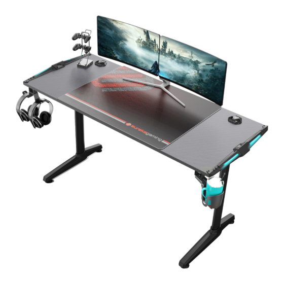
- Page 1 Electric Height Adjustable Standing Gaming Desk...
-
Page 2: Safety And Warnings
• Children should never use the desk unless they are supervised by adults. LIABILITY: This Eureka Ergonomic product is backed by a Three-Year Limited Warranty and a 30-day Risk-Free Purchase Guarantee. If it does not work the way we promised, we'll make it right. Under no circumstances does the manufacturer accept warranty claims or liability claims for damages caused from improper use or handling of the desk frame other than that which is described in this operation manual. -
Page 3: Tools Required
TOOLS REQUIRED Philips screwdriver and/or power drill Tape measure 844-416-2090 844-416-2090 www.eurekaergonomic.com customerservice@eurekaergonomic.com... -
Page 4: Parts List & Exploded View
PARTS LIST & EXPLODED VIEW Desk base Fixed part Motor chamber Crossbar end Sliding rail Storage Box Desktop Storage box buckle Protective ring Leveling stud Control box Cover rin Magnetic sheet Hand Controller Power wire Adhesive cable clips M6*20 M4*10 M6*12 Philips screwdriver M4*16... - Page 5 1.1. Attach the leveling stud to the bottom of desk base. M4*10 1.2. Use a Phillips screwdriver to loosen the M4*10 screws of fixing plate that are affixed to the left/right of the motor chambers (4 PCS for left and right sides)
- Page 6 2.1. Put the covering plate on outer tubes of the motor chamber (both left and right). 2.2. Attach each desk base to the motor chamber using 8 x (M6*20) screws.
- Page 7 M8*16 3.1. Loosen four screws(M8*16) on the left/right of the motor chamber. 3.2. Use six (M6*12) screws to connect the crossbar ends to the sliding rail, paying attention to the two screw holes in the base plate.
- Page 8 4.1. Lift the plastic cover on the motor chamber, and then buckle the fixed connection slot in the middle. 4.2. Secure the Crossbar ends to the motor chambers using 8x (M6*12) screws. M8*16 4.3. Tighten down the 4 screws you loosened in Fig. 3.1.
- Page 9 With an assistant,turn the desk base over so that the crossbar is in the upright position. Install four Protective rings Attach 2PCS storage box clips left/right to crossbar end.
- Page 10 6.1. Attach the storage box to the storage box clips. 6.2. Install the control box in the crossbar and using an M6*12 screw, secure the control box on the left.
- Page 11 Power wire Motor wire Motor wire Hand controller wire...
- Page 12 8.1. Use four screws(M4*10) to tighten the motor chamber left/right and the decoration fixed assembly. 8.2. Tighten the desktop and decorative fixed assembly left/right with four screws (M4*16). Align to the holes provided in the desktop.
- Page 13 Once you have completed installation, connect the power supply to wall power and raise the table to its maximum height and proceed to the following steps. x 10 9.1. Use ten screws(M4*16) to lock the decorative fixed assembly left/right,crossbar end, hand controller and desktop.
- Page 14 Place the 2 included magnetic sheets (have the surface with 3MM glue facing up) on the magnet of the storage box, and then remove the sheet covering the glue on the surface. Then rotate the stor- age box up, and let the magnetic sheet stick to the desktop.
-
Page 15: Desk Placement
MAX 330 LB. DESK PLACEMENT Following desk assembly, adjust the Leveling studs or casters (sold separately) on the feet so that the desk is level and does not shift its position. When moving the desk, if casters are not installed, use a two-person lift and lift the desk so that it can be moved without dragging. -
Page 16: Technical Specifications
INTELLIGENT HEIGHT MEMORY SETTINGS 1.Desktop height memory position setting Run mode, by pressing the up / down button to adjust the desktop to the appropriate height,And then press M and 1/2/3/4 of any one of them for 2 seconds, you can remember to save the desktop height.Canremember a total of four desktop height.For example: set the 3-key memory desktop height of 105, the current height of 90, press the key to run the desktop to 105, and then press the M +3 key, 2 seconds after the controller will flash the number 105, that memory is successful.
Need help?
Do you have a question about the ERK-EDK-GD and is the answer not in the manual?
Questions and answers