Table of Contents
Advertisement
Western Products, PO Box 245038, Milwaukee, WI 53224‑9538 • www.westernplows.com
74300, 74300‑1, 74300‑3, 74310, 74310‑1, 74310‑3, 74400,
74400‑1, 74400‑3, 74475, 74485, 74495, 74499, 74500‑3,
74510‑3, 74585, 74595, 74600‑3, 74675, 74685, 74695, 74699
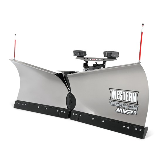
MVP 3™ Snowplow
Installation Instructions
CAUTION
Read this document before installing the
snowplow.
CAUTION
See your WESTERN
outlet/website for specific
®
vehicle application recommendations before
installation. The Quick Match selection system
has specific vehicle and snowplow requirements.
A DIVISION OF DOUGLAS DYNAMICS, LLC
July 15, 2020
Lit. No. 43071, Rev. 08
Advertisement
Table of Contents


Need help?
Do you have a question about the UltraMount 2 MVP3 74300 and is the answer not in the manual?
Questions and answers