Table of Contents
Advertisement
Quick Links
Advertisement
Table of Contents
Troubleshooting

Subscribe to Our Youtube Channel
Related Manuals for Blue Giant BGL-22


Summary of Contents for Blue Giant BGL-22
- Page 1 OWNER’S MANUAL BGL-22 WALKIE COUNTERBALANCED STACKER WARNING Do not operate or service this product unless you have read and fully understand the entire contents of this manual. Failure to do so may result in property damage, bodily injury or death.
- Page 2 WARNING Do not operate this truck unless you have been autho- Do not overload truck. Check nameplate for capacity rized and trained to do so, and have read all warnings and load center information. and instructions in Operator’s Manual and on this When using forks, space forks as far apart as load will truck.
-
Page 3: Table Of Contents
TABLE OF CONTENTS Section Page Section Page 1 DESCRIPTION ............1-1 5-3. COMPARTMENT COVERS......5-6 1-1. INTRODUCTION..........1-1 5-3.1. REMOVAL............5-6 1-2. GENERAL DESCRIPTION.......1-1 5-3.2. INSTALLATION..........5-6 1-3. SAFETY FEATURES........1-1 6 BRAKE SERVICING ........... 6-1 2 OPERATION ...............2-1 6-1. - Page 4 Page Figure Page NAME PLATE............1-1 SECONDARY LIFT CYLINDER (TRIMAST) ..9-12 BGL-22 LIFT TRUCK..........1-2 TILT CYLINDER MOUNTING......9-13 LOAD CENTER ............. 2-1 9-10 TILT CYLINDER ..........9-15 SAMPLE OF OPERATOR CHECK LIST....2-3 10-1 ELECTRICAL SYSTEM ........10-2 FORWARD/REVERSE CONTROL .......
-
Page 5: Description
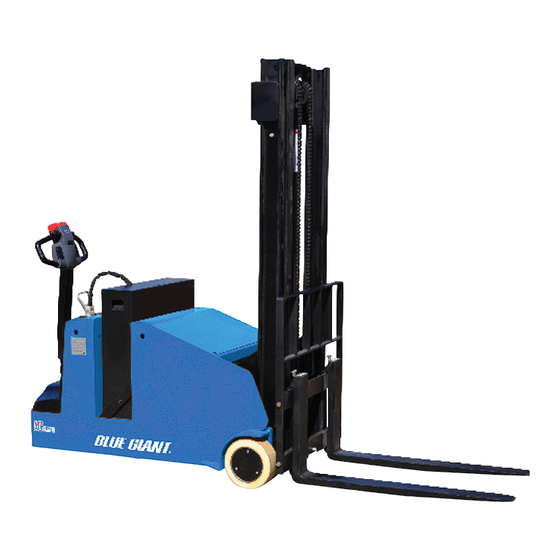
The reversible AC motor propels the lift truck in for- carriage is raised above the preset limit. ward or reverse direction throughout the available speed range. The BGL-22 lift truck can be driven • All control functions automatically return to “OFF” when released. - Page 6 R6898 Figure 1-2. BGL-22 Lift Truck ITEM COMPONENT ITEM COMPONENT Mast Chassis Back Rest Cover Forks Drive wheel Load Wheel Cover Hydraulic pump Control Handle Battery Battery Indicator Battery Disconnect Key Switch Front cover...
-
Page 7: Operation
This section gives detailed operating instructions for loaded. the BGL-22 lift truck. The instructions are divided into • Be sure that mast is vertical - do not operate on a the various phases of operations, such as operating side slope. -
Page 8: Before Operation
Do not make any unauthorized repairs or adjustments. All Table 2-1 covers important inspection points on the BGL-22 lift truck which should be checked prior to service must be performed by a qualified maintenance technician. opera-tion. Depending on use, some trucks may require additional checks. -
Page 9: Sample Of Operator Check List
Electric Truck Daily Operator Check-Off List Date Operator Truck No. Model No. Dept. Shift Hour Meter Reading Drive Hoist Check O.K. ( ) Need Maintenance Tires Load Wheels Horn Lift Lower Control Attachment Operation Forward & Reverse Controls Steering Brakes Hydraulic Leaks, Cylinders, Valves, Hoses, Etc. -
Page 10: General Control Operation
2-4. GENERAL CONTROL OPERATION. Lower the steering arm to a comfortable position above horizontal to disengage the brake and to The speed control (See Figure 2-3) located on each energize the electrical circuits. If the truck is not side of the control head provides fingertip control for moved, the electrical circuits will time out and will driving the truck. -
Page 11: Belly-Button Switch
2-7. STEERING ARM GAS SPRING. The steering arm gas spring automatically raises the steering arm to the upright position when the steering arm is released. If the steering arm does not return fully, the steering arm gas spring requires replace- ment. - Page 12 NOTES...
-
Page 13: Planned Maintenance
Leakage voltage from battery terminals to battery case accordingly. These procedures must be performed by can cause misleading trouble symptoms with the truck a qualified service technician or your Blue Giant Ser- electrical system. Since components of the truck elec- vice Representative. -
Page 14: 3-3.2. Safety Rules
Although a leakage voltage reading of zero volts may Charge the battery only in areas designated for not be possible, a cleaner battery will have more that use. usable charge for truck operation and not affect opera- Make certain the charger being used matches the tion of electronic devices on the unit. -
Page 15: 3-3.5. Maintenance Free Batteries
3-3.5. MAINTENANCE FREE BATTERIES 3-4. CHARGING BATTERIES Some trucks may be equipped with maintenance free Charging requirements will vary depending on depth batteries. These batteries are completely sealed, will of discharge and temperature. Follow safety rules not require any watering and have a full 80% dis- when placing a battery on charge. -
Page 16: Lubrication
3-5. LUBRICATION. Table 3-2 Recommended Lubricants (See Table 3-3 for Application) Refer to Table 3-2 for the recommended types of No. 1 Transmission oil—EP SAE 80W-90 grease and oil. Table 3-3 in conjunction with Figure 3- Transmission oil—EP SAE 10W-30 (Note) identifies the items requiring lubrication. -
Page 17: Lubrication Diagram
R6901 Figure 3-1 Lubrication Diagram Table 3-3 Lubrication Chart FIG 3-1 LOCATION METHOD OF TYPE APPLICATION INDEX APPLICATION (Table 3-3) LUBRICANT Inner & Outer Mast Brush No. 2 Full length of channel where rollers operate. Lift Chain Brush or Spray No. - Page 18 NOTES...
-
Page 19: Troubleshooting
SECTION 4 TROUBLESHOOTING 4-1. GENERAL Operate: Truck Does Not Operate Forward or Reverse: Trouble With Braking: Trouble With Lifting Or Table 4-1 as a guide to determine possible Lowering, and Miscellaneous malfunctions. causes of trouble. The table is divided into five main categories: Truck and Hydraulic System Will Not Table 4-1 Troubleshooting Chart MALFUNCTION... -
Page 20: Hydraulic System
Table 4-1 Troubleshooting Chart - Continued MALFUNCTION PROBABLE CAUSE CORRECTIVE ACTION TROUBLE WITH BRAKING - Continued Brake will not release. a. Defective electric brake (1, Fig- Replace brake. 12-5). b. Brake temperature above Allow to cool. 281° F (140° C). c. - Page 21 Table 4-1 Troubleshooting Chart - Continued MALFUNCTION PROBABLE CAUSE CORRECTIVE ACTION TROUBLE WITH LIFTING OR LOWERING - Continued Forks lift, but will not go down. Defect in hydraulic system Check lowering control switch in control head, lowering relays (15 & 16, Figure 12-22) &...
-
Page 22: Controller Troubleshooting
This function permits a deeper diagnosis of problems changes of the controller. The Zapi Handset is avail- as the recent history can be revisited. able through your Blue Giant dealer. If you require 4-2.2.2. Logbook Access dealer location information, contact Blue Giant. -
Page 23: 4-2.4. Settings And Adjustments
4-2.4. Settings and Adjustments 4-2.4.1. Set Options To set options proceed as follows and refer to Table 4- Connect the Zapi Handset, refer to paragraph 4-2.1. Press the ROLL up button (1, Figure 4-2) and the SET up button (5) at the same time to enter the CONFIG MENU. - Page 24 Table 4-2 Set Options - Continued Parameter Factory Setting Description SET INPUT #2 PRESENT It can be can be set as: • PRESENT: CNA#14 (Table 4-5) is managed as a cutback speed input (SR#2). • OPTION #1: CNA#14 (Table 4-5) is managed as an inching back- ward.
- Page 25 Table 4-2 Set Options - Continued Parameter Factory Setting Description AUX OUTPUT #1 BRAKE This option handles output CNA#3 (Table 4-5). It can be used as: • BRAKE: CNA#3 (Table 4-5) drives an electromechanical Brake. • HYDROCOMNT: CNA#3 (Table 4-5) drives the contractor for a hydraulic steering function when the direction input or brake pedal input are active or a movement of the truck is detected.
- Page 26 Table 4-2 Set Options - Continued Parameter Factory Setting Description AUX VOLTAGE #1 100% This option specifies the percentage of the keyswitch controlled voltage to be applied to the loads on CNA#1 (Table 4-5) (main contactor coil) and CNA#3 (Table 4-5) (electromechanical brake).
-
Page 27: Zapi Handset
4-2.4.2. Adjustments To change an adjustment proceed as follows and refer Table 4-3: Connect the Zapi Handset, refer to paragraph 4-2.1. Press the ROLL up button (1, Figure 4-3) and the SET up button (5) at the same time to enter the CONFIG MENU. - Page 28 Table 4-3 Adjustments - Continued Parameter Factory Setting Description THROTTLE X POINT This parameter together with the THROTTLE Y POINT, changes the characteristic of the accelerator input curve: when the acceler- ator is de-pressed to X point percent, the corresponding truck speed is Y point percent of the Maximum truck speed.
-
Page 29: Zapi Handset
4-2.4.3. Parameter Change To change a parameter proceed as follows and refer Table 4-4: Connect the Zapi Handset, refer to paragraph 4-2.1. Press the ROLL down button (1, Figure 4-5) and the ENTER button (3) at the same time to enter the MAIN MENU. - Page 30 Table 4-4 Parameter Adjustments - Continued Parameter Factory Setting Description CUTBACK SPEED 100% Typically from 10% to 100%. It determines the percentage of the max speed applied when the cutback switch 1 (SR#1 on CNA#15 (Table 4-5) is active. When set to 100% the speed reduction is ineffective.
-
Page 31: Zapi Controller
R6628 Figure 4-6 Zapi Controller Connections Table 4-5 Zapi Controller Connector Pins CNA Connector ABBREVATION DESCRIPTION CNA#1 Negative of main contactor coil. CNA#2 Positive of main contactor coil. CNA#3 Output for driving the electromechanical brake coil; drives the load to -Batt. Maximum current: 3 A. CNA#4 Negative of pump contactor soil. - Page 32 Table 4-5 Zapi Controller Connector Pins - Continued CNA Connector - Continued ABBREVATION DESCRIPTION CNA#12 -BATT -Batt. CNA#13 MOT TH Motor thermal sensor input. The internal pull-up is a fixed 2mA (Max 5V) source current. CNA#14 Speed reduction 2 input. Active low (switch opened). CNA#15 Speed reduction 1 input.
- Page 33 Table 4-5 Zapi Controller Connector Pins - Continued CNC Connector CONNECTOR ABBREVATION DESCRIPTION CNC#1 PCLRXD Positive serial reception. CNC#2 NCLRXD Negative serial reception. CNC#3 PCLTXD Positive serial transmission. CNC#4 NCLTXD Negative serial transmission. CNC#5 Negative console power supply. CNC#6 +12V Positive console power supply.
- Page 34 NOTES...
-
Page 35: Steering Arm, Control Head And Compartment
SECTION 5 STEERING ARM, CONTROL HEAD AND COMPARTMENT 5-1. CONTROL HEAD Remove four screws (17, Figure 5-1), lift up cap assembly (21) and disconnect harness (23) from 5-1.1. Cap Assembly Removal. harness (28, Figure 5-2). Turn off the key switch (6, Figure 12-22) and dis- connect the batteries. -
Page 36: 5-1.2. Cap Assembly Installation
5-1.2. Cap Assembly Installation. Position cap assembly (21, Figure 5-1) on control head and secure with four screws (17). Hold cap assembly (21, Figure 5-1) in place and Reconnect the batteries and turn on the key connect harness (23) to harness (28, Figure 5-2). -
Page 37: 5-1.3. Control Head Removal
5-1.3. Control Head Removal Install control knob (14) on potentiometer (15) and secure with screw (4), and washer (3). Remove the cap assembly as described in para- 10. Install control knob (2) on the other side of poten- graph 5-1.1. tiometer (15) and secure with screw (4), and Disconnect harness (28, Figure... -
Page 38: 5-1.8. Lift And Lower Switch
R6810 Figure 5-3 Emergency Reverse Switch Assembly Position the new switch in bracket (14) and Remove switch assembly (1, Figure 5-4) form cap secure with two pins (12). (17). Position bracket (14) in cover (17) and secure Remove pin (6) securing bracket (5) and remove with three screws (11). -
Page 39: Cap Assembly
R6878 Figure 5-4 Cap Assembly... -
Page 40: 5-1.9. Tilt Switch Replacement
Position the new switches and four springs (4) in Install middle cover (5, Figure 12-6) and secure bracket (5) and secure with two pins (6). with two screws (4). Position switch assembly (1) in cover (17) and Reconnect the batteries and turn on the key secure with pin (6). -
Page 41: Brake Servicing
SECTION 6 BRAKE SERVICING 6-1. BRAKES. Disconnect electric brake (1, Figure 6-1) from the harness (1, Figure 12-25). The brake system consists of a drive motor mounted Remove three screws (2, Figure 6-1) and remove brake. This brake is spring applied and electrically brake (1). -
Page 42: Transmission, Motor, Brake Assembly
R6879 Figure 6-1 Transmission, Motor, Brake Assembly... -
Page 43: Transmission, Drive Wheel, Load Wheel
SECTION 7 TRANSMISSION, DRIVE WHEEL, LOAD WHEEL 7-1. Drive Wheel. Install new transmission by reversing the steps above. Turn off the key switch (6, Figure 12-22) and dis- connect the batteries. 7-3. Load Wheel. Remove the compartment covers as described in paragraph 5-3. -
Page 44: Transmission, Motor, Brake Assembly
R6879 Figure 7-1 Transmission, Motor, Brake Assembly... -
Page 45: Load Wheels
R6882 Figure 7-2 Load Wheels... - Page 46 NOTES...
-
Page 47: Elevation System Servicing
SECTION 8 ELEVATION SYSTEM SERVICING 8-1. GENERAL. The elevation system includes the outer mast, inner mast, lift linkage, lift chains, lift cylinder and ram head. 8-2. LIFT CHAIN LENGTH ADJUSTMENT. 8-2.1. Telescopic Fully lower the lift carriage. Turn off the key switch (6, Figure 12-22) and dis- connect the batteries. -
Page 48: Elevation System (Telescopic)
R6883 Figure 8-2 Elevation System (Telescopic) -
Page 49: 8-2.2. Trimast Free Lift Chain
8-2.2. TRIMAST Free Lift Chain Loosen jam nuts (2, Figure 8-1), the mount of outer mast (25, Figure 8-3), to allow for adjust- Fully lower the lift carriage. ment of middle jam nut. Turn off the key switch (6, Figure 12-22) and dis- Break the lower jam nuts (2, Figure... - Page 50 R6884 Figure 8-3 Mast (TRIMAST)
-
Page 51: Lift Chain Replacement
8-4. LIFT CHAIN REPLACEMENT. Remove cotter pin (3) and clevis pin (4) connect- ing chain (5) to chain anchor (1) at free lift cylinder 8-4.1. Telescopic (44, Figure 8-3). With the lift truck wheels securely blocked, raise Remove chain from sheave (7). the forks approximately three feet from floor and Position new chain on sheave (7). - Page 52 NOTES...
-
Page 53: Hydraulic System Servicing
SECTION 9 HYDRAULIC SYSTEM SERVICING 9-1. LINES AND FITTINGS 9-2. HYDRAULIC PUMP, AND MOTOR ASSY WARNING: When forks are raised, pressure exists in WARNING: When forks are raised. pressure exists in the hydraulic system lines and fittings. the hydraulic system lines and fittings. To ensure release of pressure, forks To ensure release of pressure, forks must be fully lowered and the batteries... - Page 54 R6886 Figure 9-1 Hydraulic System...
-
Page 55: 9-2.3. Installation
9-2.3. Installation Connect electrical leads to pump and motor (5). Fill the hydraulic reservoir. Use hydraulic oil listed Install pump and motor assy (5, Figure 9-1) on Table 3-2. reservoir (9) and secure with four bolts (8) and four lock washers (7). Reconnect the batteries and turn on the keyswitch Figure 12-22). - Page 56 R6888 Figure 9-3 Hydraulic System (TRIMAST)
-
Page 57: Lift Cylinder (Telescopic)
9-3. Lift Cylinder (Telescopic) Remove bushing (4) and bearing (5) Remove piston (2) and O-ring (3) from rod (1). 9-3.1. Removal Remove packing (11) and backup ring (10) from With the lift truck wheels securely blocked, raise piston (1). the forks approximately three feet from floor and position blocks or strong supports under inner Coat all parts with hydraulic oil (Table... -
Page 58: Elevation System (Telescopic)
R6883 Figure 9-4 Elevation System (Telescopic) -
Page 59: Lift Cylinder (Telescopic)
R6889 Figure 9-5 Lift Cylinder (Telescopic) -
Page 60: Lift Cylinder (Trimast Free Lift)
9-4. Lift Cylinder (TRIMAST Free Lift) Remove wiper (1), collar (2), packing (3) and O- ring (5) from gland nut (4). 9-4.1. Removal Pull out piston rod (6). Fully lower the lift carriage. Remove ring (7) from piston rod (6). Turn off the key switch (6, Figure 12-22) and dis-... -
Page 61: Elevation System (Trimast)
R6884 Figure 9-6 Elevation System (TRIMAST) - Page 62 R6890 Figure 9-7 Free Lift Cylinder (TRIMAST)
-
Page 63: Lift Cylinder (Trimast Secondary)
9-5. Lift Cylinder (TRIMAST Secondary) Pull out piston rod (5). Remove backup ring (8), retaining ring (7) and 9-5.1. Removal bushing (6) from piston rod (5). Fully lower the lift carriage. Coat all parts with hydraulic oil (Table 3-2). Turn off the key switch (6, Figure 12-22) and dis- Install backup ring (8), retaining ring (7) and bush-... - Page 64 R6891 Figure 9-8 Secondary Lift Cylinder (TRIMAST)
-
Page 65: 9-5.4. Tilt Cylinders
9-5.4. Tilt Cylinders CAUTION: Hydraulic oil can damage parts. Wipe off any oil immediately. Provide a container 9-5.4.1.Removal under the line or fitting before discon- necting. WARNING: Mast must be supported by a hoist before removing the tilt cylinders. Remove the front compartment covers as described in paragraph 5-3. - Page 66 9-5.4.2.Repair 14. Install gland nut (11) in tube (17). 15. Install retaining rings (3) and bearing (2) in clevis CAUTION: To prevent damage, use proper pipe (1). clamp vise. The cylinder will be distorted if the vise is tightened too much. 16.
- Page 67 R6893 Figure 9-10 Tilt Cylinder...
- Page 68 NOTES...
-
Page 69: Electrical Components
SECTION 10 ELECTRICAL COMPONENTS 10-1.ELECTRICAL CONTROL PANEL Remove the compartment covers as described in paragraph 5-3. 10-1.1.Maintenance Tag and disconnect all electrical cables which connect to the control panel (5, Figure 10-1). NOTE: Erratic operation of the truck may be caused by defective controller components. - Page 70 R6478 R6894 Figure 10-1 Electrical System...
- Page 71 R6478 R6895 Figure 10-2 Electrical Panel...
-
Page 72: Pump Motor
10-3.PUMP MOTOR. Reinstall eight screws (4), eight lock washers (5) and eight flat washers (6) to secure the motor to Refer to paragraph 9-2. the transmission. Install brake plate (17, Figure 12-1) on the motor 10-4.DRIVE MOTOR. and secure with three screws (26) and three lock The drive motor exposed surfaces should be cleaned washers (27) at least once a month to assure proper cooling of... - Page 73 R6879 Figure 10-3 Transmission, Motor, Brake Assembly...
- Page 74 NOTES...
- Page 75 SECTION 11 OPTIONAL EQUIPMENT...
- Page 76 NOTES...
-
Page 77: Illustrated Parts Breakdown
SECTION 12 ILLUSTRATED PARTS BREAKDOWN Following is an illustrated parts breakdown of assemblies and parts associated with the BGL-22 Lift Truck. - Page 78 R6876 Figure 12-1 Steering System...
- Page 79 INDEX PART INDEX PART PART NAME REQD. PART NAME REQD. — 1120-300004-00 FIXED PLATE CONTROL HEAD (FIGURE 12-2) 1120-30000‘1-0A BRAKE PLATE 1120-330000-0A STEERING ARM 1120-300006-00 BRACKET 1120-320000-00 GAS SPRING 0000-000088-00 SCREW, M4 X 8 0000-000322-00 SCREW, M8 X 25 0000-000122-00 WASHER, LOCK, M4 1120-300003-00 SHAFT...
-
Page 80: Control Head
R6877 Figure 12-2 Control Head... - Page 81 INDEX PART INDEX PART PART NAME REQD. PART NAME REQD. — 0000-000004-00 • SCREW, M5 X 12 2320-310000-00-B CONTROL HEAD 0000-000035-00 • SCREW, M5 X 20 0000-000010-00 • SCREW, M5 X 6 1120-340002-00 • COVER 1120-340005-00 • CONTROL KNOB 1120-341000-00 •...
- Page 82 R6878 Figure 12-3 Cap Assembly...
- Page 83 INDEX PART INDEX PART PART NAME REQD. PART NAME REQD. — 2320-311102-00 • BUTTON, TILT FORWARD, 2320-311000-00 CAP ASSEMBLY LEFT 1120-342200-00 • LIFT/LOWERING SWITCH 1120-342101-00 • BRACKET, LEFT ASSY, RIGHT 1120-342002-00 • HORN BUTTON 2320-311100-00 • TILT SWITCH ASSY, LEFT 0000-000039-00 •...
- Page 84 R6810 Figure 12-4 Emergency Reverse Switch Assembly INDEX PART INDEX PART PART NAME REQD. PART NAME REQD. 1120-342005-00 • PIN — 1120-343000-00 EMERGENCY REVERSE SWITCH ASSY 1120-343001-0A • BRACKET 1120-343002-00 • EMERGENCY REVERSE 1120-343004-00 • PIN BUTTON 1120-343003-00 • SPRING...
- Page 85 NOTES...
- Page 86 R6879 Figure 12-5 Transmission, Motor, Brake Assembly...
- Page 87 INDEX PART INDEX PART PART NAME REQD. PART NAME REQD. 1120-230000-00 BEARING 1120-210000-00 BRAKE ASSEMBLY 0000-000013-00 GREASE FITTING, M8 0000-000027-00 • SCREW, M6 X 55 4230-210000-00 TRANSMISSION 1120-210002-00 • ROTOR 1120-200001-00 DRIVE WHEEL 0000-000169-00 SCREW, M8 X 30 0000-000025-00 WASHER, LOCK, M12 0000-000159-00 WASHER, LOCK, M8 0000-000157-00...
- Page 88 R6880 Figure 12-6 Compartment INDEX PART INDEX PART PART NAME REQD. PART NAME REQD. 0000-000126-00 SCREW, M6 X 16 0000-000368-00 SCREW, M8 X 12 1120-150002-00 MIDDLE COVER 2214-150002-00 WASHER 2125-140001-00 LOWER COVER 2125-140002-00 UPPER COVER...
- Page 89 NOTES...
- Page 90 R6881 Figure 12-7 Frame...
- Page 91 INDEX PART INDEX PART PART NAME REQD. PART NAME REQD. 2320-110000-00 FRAME 0000-000738-00 SCREW, M8 X 30 0000-000373-00 WASHER, FLAT, M12 2320-100004-00 PLATE 0000-000060-00 WASHER, LOCK, M12 0000-000368-00 SCREW, M8 X 12 0000-000623-00 BOLT, M12 X 30 2320-100002-00 COVER 2320-140000-00 COUNTERWEIGHT, UPPER 2320-100001-00 TOP COVER...
- Page 92 R6882 Figure 12-8 Load Wheels...
- Page 93 INDEX PART INDEX PART PART NAME REQD. PART NAME REQD. 2320-600001-00 BRACKET 0000-000851-00 SCREW, M8 X 12 0000-000233-00 WASHER, FLAT, M14 2320-600003-00 COVER 0000-000379-00 WASHER, LOCK, M14 0000-000620-00 BOLT, M6 X 16 0000-000848-00 BOLT, M14 X 85 0000-000056-00 WASHER, LOCK, M6 0000-000858-00 BUSHING, 50 X 60 X 30 0000-000380-00...
- Page 94 R6883 Figure 12-9 Elevation System (Telescopic)
- Page 95 INDEX PART INDEX PART PART NAME REQD. PART NAME REQD. 0000-000001-00 SCREW, M6 X 20 2125-612000-00 ROLLER ASSEMBLY 2125-600005-00 BUFFER BLOCK 2125-612005-00 • DUST SEAL 0000-000075-00 SCREW, M12 X 30 2125-612002-00 • ROLLER 0000-000630-00 NUT, M12 2125-612001-00 • MAIN ROLLER 0000-000108-00 NUT, M6 2125-612007-00...
- Page 96 R6884 Figure 12-10 Elevation System (TRIMAST)
- Page 97 INDEX PART INDEX PART PART NAME REQD. PART NAME REQD. 0000-000244-00 BOLT, M10 X 30 0000-000324-00 SCREW, M10 X 30 OUTER MAST 0000-000063-00 WASHER, LOCK, M10 2125-610000-30-01 (157 IN LIFT) 0000-000551-00 WASHER, FLAT, M10 2125-610000-30-02 (177 IN LIFT) 2125-600007-00 BRACKET 0000-000026-00 SCREW, M8 X 30 2125-600001-30...
- Page 98 R6815 Figure 12-11 Lift Carriage...
- Page 99 INDEX PART INDEX PART PART NAME REQD. PART NAME REQD. 2125-612005-00 • DUST SEAL 0000-000221-00 BOLT, M12 X 30 0000-000183-00 • RETAINING RING 0000-000060-00 WASHER, LOCK, M12 2125-631000-00 CARRIAGE (TELESCOPIC) 0000-000373-00 WASHER, FLAT, M12 2320-640000-30 CARRIAGE (TRIMAST) 2125-631100-00 ROLLER ASSEMBLY 2125-630001-00 FORK 2125-631104-00...
- Page 100 INDEX PART PART NAME REQD. 2125-640001-00 ADJUSTING SCREW (MAST) 0000-000187-00 NUT, M16 X 1.5 0000-000188-00 PIN, COTTER 2125-640002-00 CHAIN, TELESCOPIC 2125-640000-00-01 (96 IN LIFT) (85 LINKS) 2125-640000-00-02 (104 IN LIFT) (91 LINKS) 2125-640000-00-03 (115 IN LIFT) (99 LINKS) 2125-640000-00-04 (127 IN LIFT) (107 LINKS) 2125-640000-00-05 (135 IN LIFT) (111 LINKS) 2125-640000-00-06...
- Page 101 NOTES...
- Page 102 R6665 Figure 12-13 Hydraulic System...
- Page 103 INDEX PART INDEX PART PART NAME REQD. PART NAME REQD. 0000-000056-00 WASHER, LOCK, M6 000-000155-00 SCREW, M10 X 40 0000-000620-00 BOLT, M6 X 16 0000-000063-00 WASHER, LOCK, M10 2320-422000-00 HYDRAULIC RESERVOIR 0000-000007-00 WASHER, FLAT, M10 2112-410005-00 SPACER 2112-410004-00 WASHER 2702-141400-0A BOLT CONNECTOR 2320-421000-00 PUMP AND MOTOR...
- Page 104 R6886 Figure 12-14 Pump & Motor...
- Page 105 INDEX PART INDEX PART PART NAME REQD. PART NAME REQD. 2320-421011-00 CLAMP 2320-421001-00 VALVE BODY 2320-421012-00 TUBE, PLASTIC 2320-421-002-00 PUMP 2320-421013-00 FILTER, STEEL 2320-421-003-00 MOTOR 2320-421014-00 MANIFOLD 2320-421004-00 BUSHING 2320-421015-00 O-RING 2320-421005-00 COUPLIN 0000-000159-00 WASHER, LOCK, M8 2320-421006-00 SEAL KIT 0000-000110-00 SCREW, M8 X 65 2320-421007-00...
- Page 106 R6887 Figure 12-15 Hydraulic System (Telescopic) INDEX PART INDEX PART PART NAME REQD. PART NAME REQD. 0000-000069-00 • SEAL 2320-410000-00 HOSE ASSEMBLY 2402-143500-00 • BOLT, G1/4 X 35 0000-000044-00 • SEAL 2401-163500-00 • BOLT, M16 X 35...
- Page 107 NOTES...
- Page 108 R6888 Figure 12-16 Hydraulic System (TRIMAST)
- Page 109 INDEX PART INDEX PART PART NAME REQD. PART NAME REQD. HOSE 2125-400001-3A-B TUBE ASSEMBLY 2125-440000-3A-01 (157 IN LIFT) 2805-160010-20 • BOLT, M16 X 1.5 2125-440000-3A-03 (177 IN LIFT) 0000-000069-00 • SEAL 2125-450000-30-B TUBE 2125-400002-3A MANIFOLD 0000-000069-00 SEAL 2125-450000-00 RELIEF VALVE 0000-000109-00 SCREW, M8 X 16 0000-000154-00...
- Page 110 R6892 Figure 12-17 Tilt Cylinder Mounting...
- Page 111 INDEX PART INDEX PART PART NAME REQD. PART NAME REQD. 3218-840000-00 SHAFT 05782-08200A BOLT, M8 X 20 — CYLINDER, TILT (FIGURE 0000-000159-00 WASHER, LOCK, M8 12-21) 0000-000176-00 WASHER, FLAT, M8...
- Page 112 R6889 Figure 12-18 Lift Cylinder (Telescopic)
- Page 113 INDEX PART INDEX PART PART NAME REQD. PART NAME REQD. — — • PISTON ROD 2110-410000-00-06 LIFT CYLINDER (96 IN LIFT) 2125-410002-00 • PISTON — 2110-410000-00-02 LIFT CYLINDER 2125-410003-00 • COLLAR (104 IN LIFT) 2125-410006-00 • BUSHING — 2110-410000-00-03 LIFT CYLINDER 0000-000711-00 •...
-
Page 114: Free Lift Cylinder (Trimast)
R6890 Figure 12-19 Free Lift Cylinder (TRIMAST) - Page 115 INDEX PART INDEX PART PART NAME REQD. PART NAME REQD. — 0000-000046-00 • PACKING 2125-420000-30-01 LIFT CYLINDER (157 IN LIFT) 2125-420002-30 • GLAND NUT — 2125-420000-30-02 LIFT CYLINDER 0000-000685-00 • O-RING (177 IN LIFT) — • PISTON ROD 0000-000045-00 • WIPER RING 2125-420003-30 •...
- Page 116 R6891 Figure 12-20 Secondary Lift Cylinder (TRIMAST)
- Page 117 INDEX PART INDEX PART PART NAME REQD. PART NAME REQD. — — • PISTON ROD 2125-410000-30-01 LIFT CYLINDER (157 IN LIFT) 2125-410005-30 • BUSHING — 2125-410000-30-02 LIFT CYLINDER 0000-000520-00 • RETAINING RING (177 IN LIFT) 2125-410002-30 • BACKUP RING 0000-000084-00 •...
- Page 118 R6893 Figure 12-21 Tilt Cylinder...
- Page 119 INDEX PART INDEX PART PART NAME REQD. PART NAME REQD. — 3218-810005-00 • SEAL 2320-430000-00 TILT CYLINDER 58602-15T11 • GLAND NUT 58603-15T11 • CLEVIS 3218-810001--00 • BEARING 3218-810008-00 • BEARING, GE30ES 3218-810003-00 • O-RING 0000-000849-00 • RETAINING RING — • PISTON ROD 0000-000850-00 •...
- Page 120 R6894 Figure 12-22 Electrical System...
- Page 121 INDEX PART INDEX PART PART NAME REQD. PART NAME REQD. 0000-000056-00 WASHER, LOCK, M6 0000-000321-00 SCREW, M8 X 20 2320-531000-00 CONNECTOR, BATTERY 0000-000159-00 WASHER, LOCK, M8 1120-112008-00 SPACER 0000-000194-00 WASHER, FLAT, M8 1220-520007-0C BATTERY INDICATOR 1120-500003-00 HORN — 2320-520005-00 RELAY HARNESS ELECTRICAL PANEL (FIGURE 12-23)
- Page 122 R6895 Figure 12-23 Electrical Panel INDEX PART INDEX PART PART NAME REQD. PART NAME REQD. — 0000-000166-00 • NUT, M6 2125-510000-00 ELECTRICAL PANEL 1120-500005-00 • CONTACTOR 2125-510001-00 • BOARD 0000-000077-00 • SCREW, M6 X 12 0000-000128-00 • WASHER, FLAT, M5 1120-540001-00-B •...
- Page 123 NOTES...
- Page 124 R6630 Figure 12-24 Drive Motor...
- Page 125 INDEX PART INDEX PART PART NAME REQD. PART NAME REQD. — 0000-000056-00 • WASHER, LOCK, M6 1120-220000-00 DRIVE MOTOR 1120-220002-00 • BEARING 0000-000293-00 • RETAINING RING 0000-000204-00 • KEY, 3 x 5 x 13 0000-000226-00 • KEY, 6 X 6 X 16 0000-000409-00 •...
- Page 126 R6896 Figure 12-25 Wiring Harness INDEX PART INDEX PART PART NAME REQD. PART NAME REQD. 1120-500010-00 FUSE, 10A 2320-520001-00 WIRE HARNESS...
- Page 127 R6897 Figure 12-26 Wiring Cables INDEX PART INDEX PART PART NAME REQD. PART NAME REQD. 2320-530003-00 MOTOR CABLE U 2320-530007-00 PUMP POWER CABLE + 2320-530005-00 MOTOR CABLE W 2320-530006-00 PUMP POWER CABLE - 2320-530004-00 MOTOR CABLE V...
- Page 128 NOTES...
- Page 130 Corporate 410 Admiral Blvd USA 6350 Burnt Poplar Road Mississauga, ON, Canada L5T 2N6 Greensboro, NC 27409 t 905.457.3900 f 905.457.2313 www.bluegiant.com If calling within North America: t 1.800.668.7078 f 1.888.378.5781 © Copyright Blue Giant Equipment Corporation 2020...
Need help?
Do you have a question about the BGL-22 and is the answer not in the manual?
Questions and answers