
Related Manuals for BIGHORN SRGF11626


Summary of Contents for BIGHORN SRGF11626
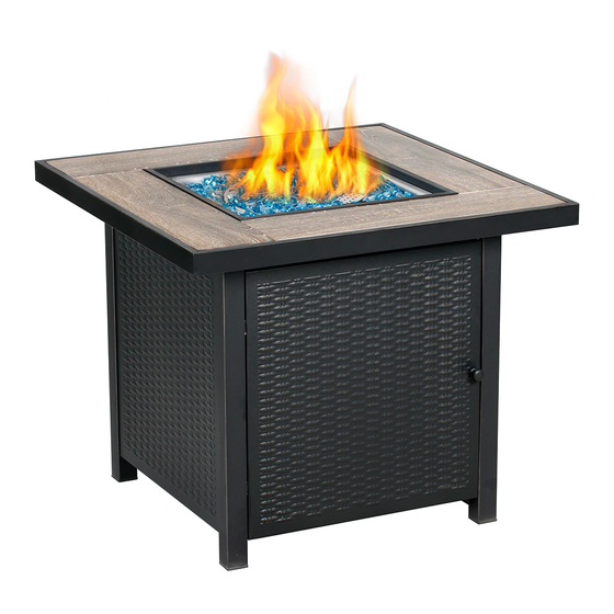
- Page 1 30" Slate Table top Gas Fire Pit Model No.: SRGF11626 0063-18 Keep the instructions for future reference.
- Page 2 WARNING 1. For use outdoors or in amply ventilated WARNING: The use of this appliance in areas. enclosed areas can be dangerous and is 2. An amply ventilated area must have a mini- PROHIBITED. mum of 25% of the surface area open. WARNING: Read the instructions before 3.
-
Page 3: Technical Data
Technical data Country Category Nominal heat Injector Gas & Pressure input(Hs) consumption diameter(Ø) 15kW 1090 g/h(G30) 1.62mm G30 Butane and 3B/P(50) G31 Propane at 50mbar 15kW 1090 g/h(G30) 1.88mm G30 Butane and 3B/P(30) G31 Propane at 30mbar 15kW 1090 g/h (G30) 1.88mm Butane 3+(28-30/37) 28-30mbar... - Page 4 Number of people required to assemble Assembly instructions Two people Find a large, clean area to assemble your appliance. Please refer to the parts list and Time to assemble assembly diagram as necessary. Please use protective gloves when assem- bling this product. 45 minutes To avoid losing any small component or hardware, assemble your product on a hard...
-
Page 5: Further Information
Further information Important Notes: Connect LP Gas cylinder LPG cylinder not provided. The appliance is Before connecting, be sure that there is no debris caught in the head of the LP tank, designed to operate with a cylinder of size Ø head of the regulator valve or in the head 31.8 x 58 cm. - Page 6 Leak testing (to be performed in a well- ventilated area) Your Outdoor appliance has been checked for leaks at all the factory made connections. To check the connection of the gas hose/regulator/LPG cylinder. 1) Make leak test solution by mixing 1 part washing up liquid and 3 parts water.
- Page 7 Minimum clearance from combustible surfaces This appliance is primarily used for the heating of outdoor patios, decks, spas, pools and open working areas. Combustible materials are considered to be wood, compressed parter, plant fibres, plas- tic or other materials that are capable of being ignited and burned.
-
Page 8: Lighting Procedure
LIGHTING PROCEDURE OPERATING PROCEDURE Note: The burner may be noisy when initially 1. Make sure control knob is in the "OFF" position. turned on, To eliminate excessive noise from 2. Turn LP cylinder gas the burner, turn the control knob to the LOW position. -
Page 9: Cleaning And Maintenance
STORAGE Cleaning and maintenance To enjoy years of outstanding performance Between uses: from your gas fire pit make sure you perform Turn the control knob to "OFF" position. the following maintenance activities on a Turn LP cylinder to OFF position. regularbasis: Allow at least 45 minutes for the fire pit to cool down after use, then disconnect and... -
Page 10: Troubleshooting
TROUBLESHOOTING PROBLEM POSSIBLE CAUSE CORRECTIVE MEASURES OBSERVED Gas odor Gas leak Check all gas connections Check gas supply pressure. Low gas pressure. Delayed ignition Clean burner parts--see manual. Clogged or dirty burner ports. "CLEANING AND MAINTENANCE" section. Incorrect burner Incorrect gas supply or pressure. Check gas supply pressure. -
Page 11: Exploded View
EXPLODED VIEW... -
Page 12: Parts & Hardware
PARTS & HARDWARE Part # Description Picture Part # Description Picture Table Top Door Door Knob Side Panel Base Frame Gas Valve Panel Back Right Leg Lava Rock Regulator Front Right Leg Hardware# Dimensions Picture M5 x 12 M5 x 12 Back Left Leg M5 x 20 M6 x 12... - Page 13 ASSEMBLY INSTRUCTIONS GAS HOSE ELECTRODE WIRE AA x 4 M5 x 12 METAL TUBE...
- Page 14 ASSEMBLY INSTRUCTIONS DD x 12 M6 x 12 BB x 6 M5 x 12...
- Page 15 ASSEMBLY INSTRUCTIONS BB x 6 M5 x 12 BB x 6 M5 x 12...
- Page 16 ASSEMBLY INSTRUCTIONS CC x 4 M5 x 20...
- Page 17 ASSEMBLY INSTRUCTIONS EE x 4 ST4.2 x 9.5...
- Page 18 ASSEMBLY INSTRUCTIONS...
Need help?
Do you have a question about the SRGF11626 and is the answer not in the manual?
Questions and answers