Advertisement
Quick Links
part
A
bike support arm
B
end cap 25 x 50 mm
C
end cap 20 x 40 mm
D
knob M6 x 1.25
E
bike holder cradles
screw, hex head, M6 x 1.00 x 10 LG
F
screw, hex head, M6 x 1.00 x 65 LG
G
H
M6 flat washer
I
leveling glide M6 x 1.00
J
structure top half
K
structure bottom leg
L
cross support brace
M
foot base
N
base support bracket
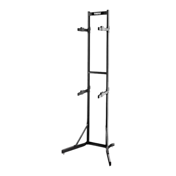
BSTK2
BIKE STACKER
PARTS INCLUDED
A
C
E
F
N
B
I
description
J
D
K
M
L
H
G
part number
qty
05-0066-000-00
4
05-0067-000-00
6
05-0068-000-00
4
05-0069-000-00
4
05-0070-000-00
4
05-0071-000-00
4
05-0072-000-00
4
951-0612-11
8
05-0073-000-00
4
—
1
—
2
—
1
—
2
—
2
Advertisement

Related Manuals for Thule BSTK2


Summary of Contents for Thule BSTK2
- Page 1 BSTK2 BIKE STACKER PARTS INCLUDED part description part number bike support arm 05-0066-000-00 end cap 25 x 50 mm 05-0067-000-00 end cap 20 x 40 mm 05-0068-000-00 knob M6 x 1.25 05-0069-000-00 bike holder cradles 05-0070-000-00 screw, hex head, M6 x 1.00 x 10 LG 05-0071-000-00 screw, hex head, M6 x 1.00 x 65 LG...
-
Page 2: Installation / Installation / Instalación
INSTALLATION / INSTALLATION / INSTALACIÓN • Line up one foot base (M), cross support brace (L) and structure bottom leg (K) as shown in the diagram. Please note that there is a right and left structure bottom leg (K). The structure bottom leg should be positioned so that the single screw hole thirteen inches above the ground is facing forward and the flat surface at the top connection faces outward to the side. - Page 3 (F) through the washers (H) and then into both the structure bottom leg (K) and the foot base (M). Tighten firmly. • Slide the structure top half (J) onto the tops of the structure bottom legs as shown. The Thule logo should be facing forward.
- Page 4 • Attach the four bike support arms (A) to the vertical side bars on the front side of the Bike Stacker structure. You should place two arms on each vertical side bar. The arms are movable and can be positioned at any height on the vertical side bars to adjust to the height of the bikes that will be placed on it.
- Page 5 • Attach the knob (D) through the backside of the top C-Shaped tab and tighten firmly. • Screw the four leveling glides (I) onto the bottom of the foot base • Slide the four bike holder cradles (E) onto the bike support arms. The indent faces upwards in the cradle to hold the bike.
- Page 6 LOADING BIKES • The Bike Stacker is designed to hold two bikes up to a combined total weight of 70 lbs. (32 kg). Measure the heights of the bikes to determine the approximate arm height settings. You can adjust the arm heights by loosening the knobs and then raising or lowering the arms before re-tightening the knobs. PLEASE NOTE YOU SHOULD ALWAYS PUT THE HEAVIER BIKE ON THE BOTTOM SET OF ARMS.
Need help?
Do you have a question about the BSTK2 and is the answer not in the manual?
Questions and answers