Table of Contents
Advertisement
Quick Links
Advertisement
Table of Contents

Subscribe to Our Youtube Channel
Related Manuals for PCB Piezotronics Larson Davis BAS002


Summary of Contents for PCB Piezotronics Larson Davis BAS002
- Page 1 Building Acoustic Source Model BAS002 Power Ampli er & Speakers Manual...
- Page 3 Larson Davis Building Acoustic Source Model BAS002 Power Amplifier & Speakers Manual IBAS.01 Rev B...
- Page 4 Copyright Copyright 2013 by PCB Piezotronics, Inc. This manual is copyrighted, with all rights reserved. The manual may not be copied in whole or in part for any use without prior written consent of PCB Piezotronics, Inc. Disclaimer The following paragraph does not apply in any state or country where such statements are not agreeable with local law: Even though PCB Piezotronics, Inc.
-
Page 5: Table Of Contents
Table of Contents Chapter 1 Introduction Components ......................1-1 Features ......................... 1-2 Safety and Care ..................... 1-5 Chapter 2 First Use Unpacking and Inspection ..................2-1 Assembling the Amplifier and Speaker ..............2-2 Installing the Remote Control Battery ..............2-2 Powering-up the Model BAS002 ................ -
Page 7: Chapter 1 Introduction
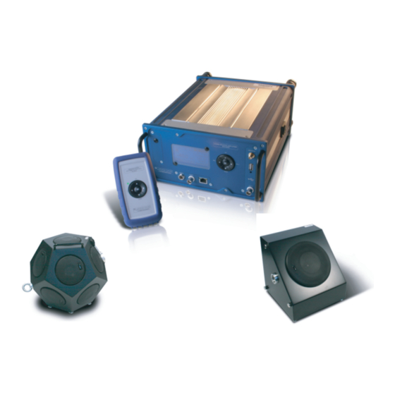
C H A P T E R Introduction This chapter describes the features, functions, and proper care of the Larson Davis Building Acoustic Source models BAS001, BAS002, and BAS003. Components Figure 1-1 shows the components of the BAS002 Power Amplifier System. FIGURE 1-1 BAS002 System Components BAS002 Introduction... -
Page 8: Features
Features The Larson Davis Model Building Acoustic Source has the following features: • High power and level output • Fast and easy-to-use • Fan-less cooling • Very low-power output distortion (THD + N < 0.12%) • Wide bandwidth • Lightweight and small-dimension components •... - Page 9 • Absorption coefficient Standards Compliance • EN ISO 10140/3 and EN ISO 10140/4 Standard (dodecahedral source) • EN ISO 140/S Standard (façade - directional source) • EN ISO 140-1 • EN ISO 3382 • ASTM E2235 • DIN210 Standard Accessories The BAS002 Power Amplifier is delivered with the following standard accessories: •...
- Page 10 Figure 1-2 shows the deployment layout for Larson Davis building acoustic source and sound level measurement products. BAS001 Dodecahedral Speaker BAS002 Amplifier CBL182 (Speakon) Speaker Cable ISM Antenna USB Device Remote BAS003 Control Directional Speaker TRP023 Speaker Tripod CBL180 Model 831 AC Out to BNC FIGURE 1-2 Deployment Layout BAS002...
-
Page 11: Safety And Care
Safety and Care Follow these safety and care guidelines for proper operation and maintenance of the system: • The amplifier and the loudspeaker are intended mainly for indoor use. Do not use the system outdoors when it is raining. • Keep the product away from any heat source or dampness. - Page 12 BAS002 Cleaning...
-
Page 13: First Use
C H A P T E R First Use This chapter outlines the steps to unpack the Model BAS002 Power Amplifier and prepare it for first use. Preparing for first use includes the following: • Unpacking and inspection • Assembling the amplifier and speaker •... -
Page 14: Assembling The Amplifier And Speaker
Assembling the Amplifier and Speaker To prepare the amplifier and connect it to the speaker, follow these steps: Remember to turn the antenna Step 1 Mount the antenna, screwing it on the gold-plated horizontally (or remove it) when connector on the on the front panel. transporting to avoid damage. -
Page 15: Powering-Up The Model Bas002
Step 3 Reassemble. FIGURE 2-1 Remote Control Bottom On the top of the remote control, press the power button to turn the remote on or off. Powering-up the Model BAS002 By default the value of the power To power up the system, press the power switch on the rear output is set to -40 dB, the amplifier panel of the amplifier. - Page 16 If an incorrect AC power voltage is supplied, the protection fuse will be blown and the amplifier will not switch on. FIGURE 2-2 BAS002 Amplifier Display The amplifier should be connnected The default source input is the USB port. The LED near the to a grounded socket.
-
Page 17: Bas002 Power Amplifier
C H A P T E R BAS002 Power Amplifier This chapter describes the components, features, and basic operation of the BAS002 power amplifier. Components and Features The BAS002 Power Amplifier generates specific signals useful for acoustic applications and tests. It can also be connected to the Model 831 sound level meter to simplify and speed up RT-60 measurements. - Page 18 The amplifier provides the following interfaces: Front Panel: Display, keypad, AUX input connector, ISM Antenna for remote control (right side panel), the ethernet connector, monitor output, and the trigger connectors. FIGURE 3-1 BAS002 Power Amplifier Front Panel BAS002...
- Page 19 Rear Panel: Power supply connecter and main power switch. FIGURE 3-2 BAS002 Rear Panel Connections POWER IN The BAS002 is powered as either 110V (U version) or 220V (E version) AC nominal voltage. Ensure that proper connection for SIGNAL OUT the signal is made by twisting the The signal/power cable to the BAS001 or BAS003 speaker connector clockwise.
- Page 20 SIGNAL IN The AUX IN or USB connection is available for input signals. ANALOG OUT This output offers the “monitor signal” that goes to the speakers before being amplified. RJ45 ETHERNET This connecter is used with control software and fixed IP addresses to remotely control the amplifier.
- Page 21 The BAS002 power amplifier display can be used with the keypad to select functions or modes. Press the up and down arrow buttons of the keypad to make selections on the right side of the display. Table 3-1 shows the keypad controls for the fields located on the right side of the BAS002 display.
- Page 22 Display Field (Right Side) Keypad Control BasBOOST Select this field and press OK to enable or dis- able. When enabled, an “F” appears in the dis- play above the “dB.” This function enhances low frequencies, below 100 Hz by pushing a 1/3 octave band up by 15 dB.
-
Page 23: Basic Operation
Status Area Indication Trigger Indicator Indicates an external trigger has been received. Remote Control Indicator Indicates a command from the remote control unit has been received. Table 3-2 BAS002 Status Display (Left Side) Basic Operation Playing Signal Files To play signal files, follow these steps: Make sure the volume is initially set Step 1 Plug in amplifier and power it up as previously to low output levels. - Page 24 Changing the Input Source To change the input source for the amplifier, select either the AUX in or the USB in field (whichever is displayed) and press OK. The input mode is switched back and forth between these options each time OK is pressed. If USB in is selected, the internal preamplifier and the analogue net are connected to the USB source.
- Page 25 Step 3 Insert the BNC connector end of CBL181 into the AUX in connector on the BAS002 amplifier. Figure 3-6 shows the connection. CBL180 and CBL181 are optional accessories. FIGURE 3-6 CBL181 Connection to Power Amplifier Setting the Timer To use the timer, select the TIMER field and press OK. The timer starts the following sequence: The amplifier pauses for a specified PauseTime.
- Page 26 Playing must be stopped manually. The file is played until the specified PlayTime has elapsed or for the duration of the file, whichever ends first. Applying the BasBOOST Enhancer To activate the BasBOOST function, select the field and press OK. BasBOOST enhances lower frequencies, with a selectable roll-off frequency and a selectable gain, and works as a FIR in the DSP.
-
Page 27: Remote Control
C H A P T E R Remote Control This chapter describes the functions and operations of the hand-held remote control. The BAS remote control operates in the ISM band at 2.4 GHz, conforming to world-wide regulatory-approved frequencies. Switch Antenna Three-color LED Keypad FIGURE 4-1 Hand-Held Remote Control... - Page 28 Features of the Remote Control The remote control unit provides a wide radio range at low power and draws low current levels by optimizing the operating and idle status. A low power microprocessor controls the functions of the radio remote control. The control also includes a range finder to indicate if the amplifier is in range and if the amplifier is playing a sound.
- Page 29 • Red steady: the remote control is not in the radio range of the amplifier. Keypad commands are transmitted by the remote control but not received by the amplifier. In this case, move closer to the amplifier until the LED is green and radio connection is re-established.
- Page 30 BAS002 Battery Replacement...
-
Page 31: Bas001 Dodecahedral Speaker
C H A P T E R BAS001 Dodecahedral Speaker This chapter describes the features and components of the BAS001 dodecahedral source speaker. The BAS001 is designed with the following specifications: • High power output • Omnidirectionality • Frequency range wide enough for efficiently reproducing the sound field from 100 Hz up to 6300Hz •... - Page 32 Additional Information The following tips may be helpful when using the speaker: • The eyebolt can be used to hang the speaker if a tripod is not a convenient solution. • The handle has been placed on the side of the speaker to help in handling and managing the device.
-
Page 33: Directional Source Bas003
C H A P T E R Directional Source BAS003 This chapter describes the features and components of the BAS003 directional source speaker. Because of its directivity, the BAS003 is designed to allow building façade testing measurements according to specified standards. - Page 34 BAS002...
-
Page 35: Software Control
C H A P T E R Software Control This chapter describes functions and controls of the BAS002 system software. Launching the Software To launch the BAS002 system software, copy the odsctrl.exe file from the supplied USB flash memory and paste it to a location on your computer. -
Page 36: Connecting The Amplifier
The BAS002 system software provides the most extended control of the system, as shown in Table 7 - 1. Remote Amplifier Software Feature/Function Control Keypad Controls Start/Stop Output Volume File Selection Input USB or AUX Standby (Mute) Timer Cycling BasBOOST Enhancer Timer Control and Setup Display Contrast Radio Power and Setup... - Page 37 FIGURE 7-2 BAS002 Software Connection Upon being launched, the software searches for a client. In this state the Connect icon is red and flashing. If the LAN AutoLink option is checked, the software searches for a BAS002 unit on the same network subnet. The static IP address of the BAS002 amplifier is always 192.168.1.2.
- Page 38 Step 2 On the Network and Sharing Center, click on the Local Area Connection link as shown in Figure 7-3. FIGURE 7-3 Local Area Connection Link Step 3 On the Local Area Connection Status dialog box, click the Properties button. BAS002 Configuring TCP/IP...
- Page 39 Step 4 On the Local Area Connection Properties dialog box, select Internet Protocol (TCP/IP) and click the Properties button, as shown in Figure 7-4. FIGURE 7-4 LAN Properties On the General tab of the Internet Protocol (TCP/IP) Properties dialog box, select the option to Use the following IP address.
-
Page 40: Selecting Usb Signal Sources
Figure 7-5 shows an example of IP address configuration. FIGURE 7-5 IP Address Configuration To simplify the connection, use a Once the connection is established, the LED on the Ethernet CAT5E cable directly port changes from a flashing red to a steady green. amplifier. - Page 41 Step 3 Once the USB files appear in the File List, select the file to be used and click Set File, as shown in Figure . Once it has been selected and set, the name of the file is also shown on the amplifier display.
-
Page 42: Selecting Aux Signal Sources
Selecting AUX Signal Sources To select AUX signal sources with the Model 831 in the BAS002 software, follow these steps: Step 1 Insert the plug end of CBL180 into the AC Out jack of the Model 831. Figure 7-8 shows the AC Out. AC Out FIGURE 7-8 Model 831 AC Out Step 2 Insert the BNC connecter end of CBL180 into the... -
Page 43: Setting Parameters
Make sure the volume is initially set Step 4 In the Volume Control area, adjust the volume by to low output levels. selecting values from the USB drop-down list. These values decrease by 1 dB from 0 to -20 dB and by 5 dB from -20 dB to -90 dB. - Page 44 Step 2 Specify the following parameters: The amplifier and the remote control • Channel ISM: Specify radio channels 10, 30, 50, or 70. must be set to the same radio • Power EIRP (Transmit Power): Specify ranges from - channel to function properly. 14, -10, -6, -1, +6, +10, +13, +15 dBm.
- Page 45 Step 2 Specify the values for each option: • Pause: Specify the Max number of seconds for the starting pause value. Specify the Current number of seconds for the on-going pause time. • Play: Specify the Max number of seconds for the starting play time.
- Page 46 • UP key function: Select a dedicated function for the up arrow key of the remote control. • DN key function: Select a dedicated function for the down arrow key of the remote control. • OK key function: Select a dedicated function for the OK key of the remote control.
-
Page 47: Using Functions
• Ramp Tick: Specify the number of steps for increasing or decreasing volume in Ramp Time. Step 3 Click Set. Using Functions The same functions available on the amplifier display menu are also available on the software interface, including: To perform any of these functions, •... - Page 48 BAS002 Audio 7-14...
-
Page 49: Appendix A Technical Specifications
A P P E N D I X Technical Specifications The specifications contained in this chapter are subject to change without notice. Please refer to calibration and measurement results for data on a specific unit. Acoustic Standards met by BAS002 Amplifier ISO 140-3:2010 When used with BAS001 ISO 140-4:2010... -
Page 50: Model Bas002 Power Amplifier Specifications
Model BAS002 Power Amplifier Specifications Physical Charcteristics Dimensions 12.2 x 9.4 x 4.7 in 31 x 24 x 12 cm Weight 8.8 lbs 4 kg Temperature Range -20°C to +70 °C Relative Humidity <90% not condensing Power Supply BAS002-U 115 V 90-132.5 VAC 55-65 Hz Fuse T6.3AH... - Page 51 Connector Impedance 50 Ω ISM Antenna Frequency Range ISM Band 2.4 GHz Gain 2 dBm Connector Type A female Version 2.0 12 Mbps Power Amplifier Output Power 0.05% Thd+n, 1khz, 4 Ω 500 W Bandwidth 4 Ω Load 5 Hz – 80 Khz Thd + N Aes17 Filter, 10hz-20khz 0.12%...
- Page 52 Supported WMA Formats Sample Bitrate (kbit/sec) rate 5 6 8 8000 11025 16000 22050 32000 44100 48000 Note: Windows Media Audio codec version 2,7,8 and 9 are supported. All WMA profiles (L1, L2 and L3) are supported. WMA9 Professional and WMA 9 Lossless are not supported. In addition to these WMA decoding profiles, all other bitrate and samplerate combinations are supported, including variable bitrate WMA streams.
- Page 53 Radio Unit Operating Band ISM - Frequency 2.4 GHz – 2.483 GHz Receiver sensitivity -95 dBm Output Power EIRP -14, -10, -6, -1, +6, +10, +13, +15 dBm Baseband GFSK Modulator DSSS Channels available from 2 to 78 – 10, 30, 50, 70 selectable Channel Separation 1 MHz Note: For European use, the maximum power level is 10mW ERP.
-
Page 54: Hand-Held Remote Control Specifications
Hand-Held Remote Control Specifications Features Wide Radio Range Worldwide Radio Standard compatibility ISM band Low power consumption & long operating time Multifunction Status Indicator Range Finder function Programmable keys Selectable Channels and Tx Power Polarity inversion protection Protecting Rubber boot Physical Characteristics Dimension 5.7 x 3.1 x 1.6 in... -
Page 55: Model Bas001 Dodecahedral Source Specifications
Model BAS001 Dodecahedral Source Specifications Features High sound power level output Acoustically Isotropic Source Frequency Response Flatness in Standards Range Lightweight Compact dimensions Physical Characteristics Dimensions (carrying case CCS044) 14½ x 14½ x 15¼ in 37 x37x39 cm Weight 17 lbs 7.7 kg Temperature Range -20°C to +70 °C... - Page 56 Min/Max Directivity Errors Equalized output power Model BAS001 Dodecahedral Source Specifications BAS002...
-
Page 57: Model Bas003 Directional Source Specifications
Directivity Model BAS003 Directional Source Specifications Features High sound power level output Acoustically Directional Source Frequency Response Flatness in Standards Range Lightweight Compact dimensions BAS002 Model BAS003 Directional Source Specifications... - Page 58 Physical Characteristics Dimensions (carrying case CCS044) 14½ x 14½ x 15¼ in 37 x37x39 cm Weight 17 lbs 7.7 kg Temperature Range -20°C to +70 °C Relative Humidity <90% not condensing Acoustical Specifications 113 dB re 1 pW (not-equalized) Sound Power 116 dB re 1 pW (equalized 50-5kHz) Sound Pressure Level 95 dB(Z) at 10 m...
- Page 59 Directivity CE Declaration of Conformity PCB Piezotronics, Inc. declares that: Model BAS002 Power Amplifier has been measured in representative configuration with: • Model BAS001 Dodecahedral Source • Model BAS003 Directional Source • Remote Control and the following cables: • CBL182 Speakon Signal Power cable •...
- Page 60 with a generated acoustic field of 115 dB of Equalized White Noise. The Model BAS002 complies with the European Community EMC Directive (2004/108/EC) and also the Low Voltage Safety Directive (2006/95/EC) by meeting the following standards: • 61326-1:2005: Electrical equipment measurement, control and laboratory use –...
-
Page 61: Appendix B Default Mp3 Files
A P P E N D I X Default MP3 Files This appendix describes the default MP3 files provided on flash memory with the BAS002, as shown below. The BAS002 display limits the actual size of the files to 8 characters. Signal Type •... - Page 62 BAS002...
-
Page 63: Appendix C Mp3 File Creation: An Example
A P P E N D I X MP3 File Creation: An Example This appendix provides an example for editing sound waves and generating MP3 files for use with the BAS002 power amplifier and speakers. Creating MP3 Signal Files: Overview The BAS002 power amplifier accepts files in MP3 format for replay. - Page 64 Step 3 Fill with noise. Click Generate > Noise. The fol- lowing Noise Generator dialog box specifies white noise for six minutes. The resulting screen allows you to verify the following: Click the Audiotrack drop-down • Mono (or Stereo) arrow to switch views. •...
- Page 65 Step 4 Sharpen frequency contents. Click Analyze > Plot Spectrum. The following dialog box appears: BAS002 Creating MP3 Signal Files: Example...
- Page 66 Step 5 Edit the graphical curve. Click Effect > Equaliza- tion. . . Use the Draw Curve mode to edit, as shown below. You can also use the Graphic EQ function to modify the curve. Creating MP3 Signal Files: Example BAS002...
- Page 67 Step 6 Normalize. Click OK, then click Effect > Nor- malize. The Normalize dialog box appears, as shown below. Although Audacity limits the dynamic range of the filter, this will be corrected automatically. BAS002 Creating MP3 Signal Files: Example...
- Page 68 Creating MP3 Signal Files: Example BAS002...
- Page 69 Step 7 View the plot spectrum. Click Analyze > Plot Spectrum. Step 8 Select the curve. Click Effect > Equalization. . . Select the eq12cawhite curve, as shown below. This curve is the BAS001 white noise inverse transfer function. BAS002 Creating MP3 Signal Files: Example...
- Page 70 Step 9 Click OK. The Equalization graph shows the curve below. Creating MP3 Signal Files: Example BAS002...
- Page 71 Step 10 Click Effect > Normalize. Then click OK. BAS002 Creating MP3 Signal Files: Example...
- Page 72 Step 11 Click Analyze > Spectrum. Note: Log frequency. C-10 Creating MP3 Signal Files: Example BAS002...
- Page 73 Step 12 Click Effect > Compressor. Compress the signal with the Dynamic Range Compressor dialog box, as shown below. BAS002 Creating MP3 Signal Files: Example C-11...
- Page 74 Step 13 Click OK. C-12 Creating MP3 Signal Files: Example BAS002...
- Page 75 Click Analyze > Plot Spectrum. For easy recognition on the BAS002 Step 14 Save as MP3 file. Click File > Export. Then display, filenames should be 8 char- select Format: MP3. acters or less. Duplicates are dis- Step 15 Transfer to USB Memory. played with the same first 6 characters but the last 2 characters •...
Need help?
Do you have a question about the Larson Davis BAS002 and is the answer not in the manual?
Questions and answers